Hiding Parts of Tilesets with Cartographic Polygons
With Cesium for Unity, you can combine terrain, photogrammetry, and other kinds of 3D geospatial data in a single Unity level. If multiple datasets overlap in coverage, however, they may intersect when placed in the same scene, causing visual artifacts. In these cases, it is useful to hide conflicting parts of the datasets to improve their combined appearance. This is made possible in Cesium for Unity through CesiumCartographicPolygon, a versatile tool for applying visual effects to 3D Tilesets.
CesiumCartographicPolygons represent polygonal areas mapped to specific points on the globe. When assigned to a Cesium3DTileset, the polygons can be used to mask and “clip” 3D data. In other words, they can define areas where 3D data is made transparent, effectively hiding it in the scene. CesiumCartographicPolygon uses splines to provide user flexibility for the shape of the polygon, allowing complex regions to be carved on the globe. Cartographic polygons offer an intuitive way to visually modify 3D Tilesets and curate their appearance.
A CesiumCartographicPolygon can even be used to apply other material effects. For instance, instead of hiding data, a CesiumCartographicPolygon can be used to highlight its contents in a bright color for visual emphasis. Ultimately, you can control how polygons work in your own 3D Tileset materials and customize their appearance.
Read on to learn how to use CesiumCartographicPolygons in your own applications.
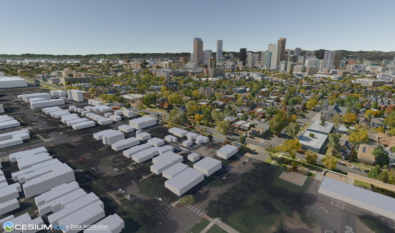
A CesiumCartographicPolygon hides Cesium OSM Buildings where they overlap with this high-resolution Denver photogrammetry model from Aerometrex.
Clipping as discussed in this tutorial refers to the visual modification of 3D tilesets. Cartographic polygons can be used to hide parts of tilesets through a material effect. They do not affect physics meshes at this time. Since this is a visual effect, you can still collide with parts of a tileset that are hidden by a polygon.
Additionally, CesiumCartographicPolygon is designed only for masking certain portions of the globe; see the Editing Cartographic Polygons section for more details.
You’ll learn how to:
- Create and shape CesiumCartographicPolygons.
- Assign polygons to tilesets using CesiumPolygonRasterOverlay.
- Apply polygon clipping and other effects in tileset materials.
- An installed version of Unity 2022.2+ or later. The latest version of Unity 2022.3+ LTS is recommended.
- Cesium for Unity v1.8.0 or later.
- Know how to set up a basic Cesium for Unity application. If you need help, check out the Cesium for Unity Quickstart guide for how to get started with the Cesium for Unity package.
- A Cesium ion account to stream terrain and building assets into Unity. Sign up for a free Cesium ion account if you don’t already have one.
CesiumCartographicPolygon requires the Unity Splines package, which is only available in versions of Unity 2022.2+. Due to this limitation, CesiumCartographicPolygon is not supported for earlier Unity versions, even when using Cesium for Unity v1.8.0 or later.
This tutorial assumes that you have already created a project and imported the Cesium for Unity package. If you have not done so yet, see the Quickstart for detailed instructions.
A CesiumCartographicPolygon requires a Spline component, which is only available through the Unity Splines package. This package won’t automatically install with Cesium for Unity, so follow the steps below to enable it in your project. Later on, you’ll learn how to create and edit a CesiumCartographicPolygon in your scene.
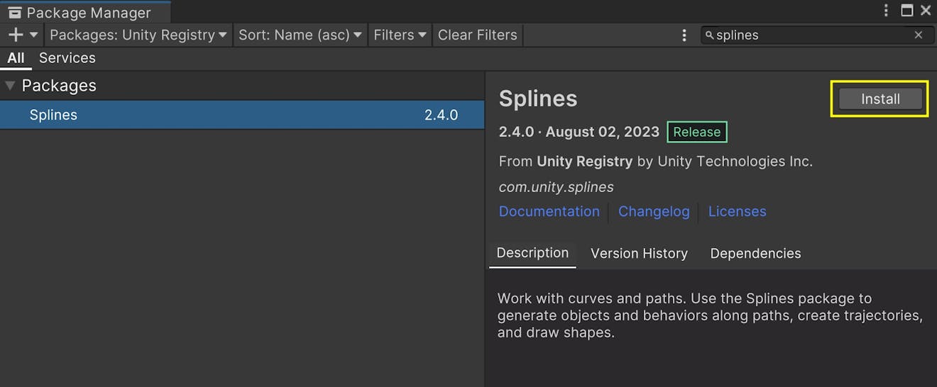
1Open the Package Manager by going to Window > Package Manager in the top menu. Make sure you are viewing packages from the Unity Registry.
2Search for and select the “Splines” package. Then, click Install.
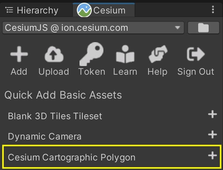
3Wait for the package to install. When done, the Editor will reload with the additions from the Splines package. Verify that you now see a Cesium Cartographic Polygon option under the Quick Add panel in the Cesium window.
Now you can create a scene in which you’ll use CesiumCartographicPolygon for clipping.
In the following steps, you’ll combine Cesium OSM Buildings with Aerometrex’s high-resolution Denver photogrammetry. Both of these datasets are available through the Cesium ion Asset Depot.
1Start with a scene that includes Cesium World Terrain + Bing Maps Aerial imagery and Cesium OSM Buildings.
You can use the first scene in Cesium for Unity Samples as a base level for your project. Otherwise, check out the Quickstart tutorial for detailed instructions on creating this scene from scratch.
2If you have not already connected to Cesium ion, do so by clicking Connect to Cesium ion in the Cesium window.
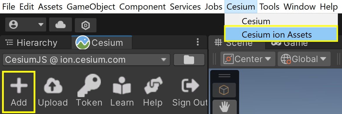
3Open the Cesium ion Assets window. If you don’t see the window in the Editor, open it using Window > Cesium ion Assets, or press the Add button in the Cesium panel.
4Find Aerometrex Denver High Resolution 3D Model in your asset list. Select it from the list, then click Add to Level.
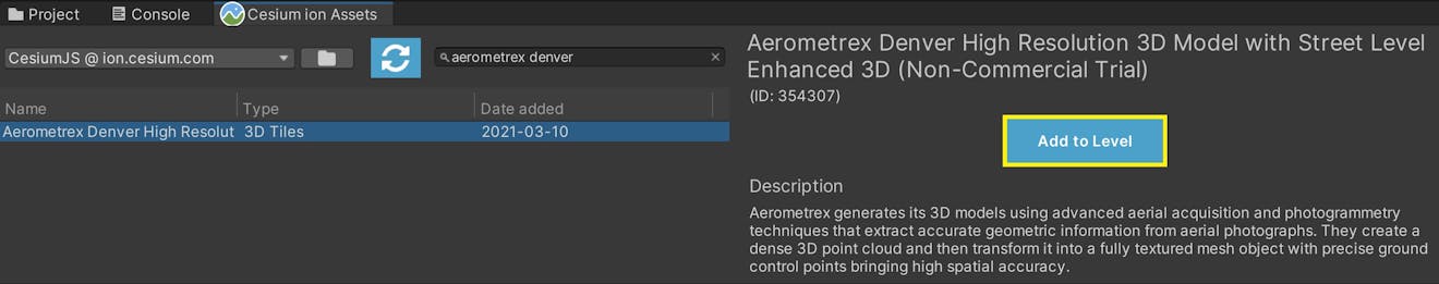
Is Aerometrex Denver High Resolution 3D Model missing from the asset list? Visit the Asset Depot page and click Add to My Assets. Then return to Unity and refresh the asset list using the button in the upper left corner of the Cesium ion Assets window.
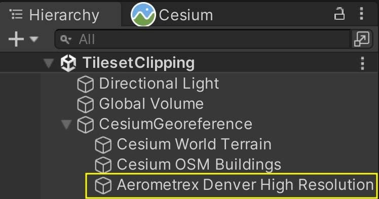
Once added, the tileset should appear under the CesiumGeoreference in your scene Hierarchy.
5Move the CesiumGeoreference origin closer to the Denver dataset. You can do this by repositioning the Editor camera, then selecting the CesiumGeoreference and using Place Georeference Origin Here. Or, you can simply copy the following values into your CesiumGeoreference.
Latitude: 39.74986
Longitude: -104.9904
Height: 2139.273
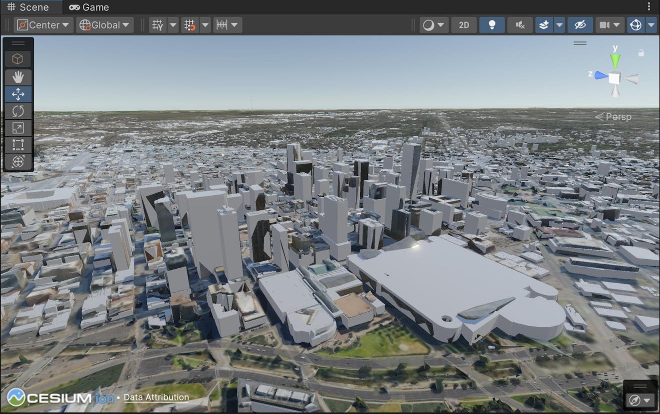
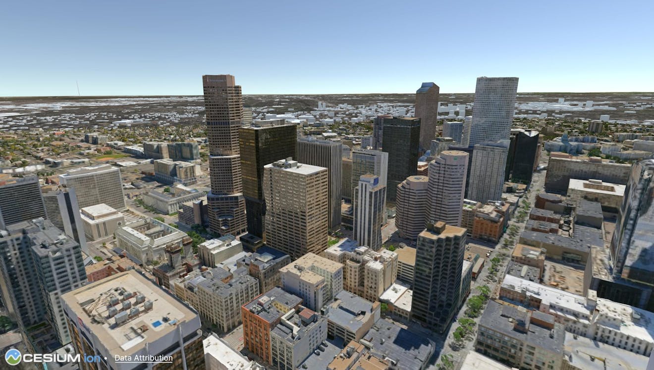
You may notice that OSM Buildings and the Denver photogrammetry overlap each other, as in the view below.
The rest of this tutorial will show how you can resolve this overlap. Before that, you may want to follow the next few steps to prepare your scene for easier spline editing.
6First, select Cesium OSM Buildings in the Hierarchy and locate the box next to its name in the Inspector.
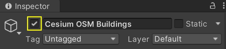
Uncheck this box to disable the game object and prevent the tileset from showing. This isolates the Aerometrex Denver dataset so that you can see its boundaries more clearly.
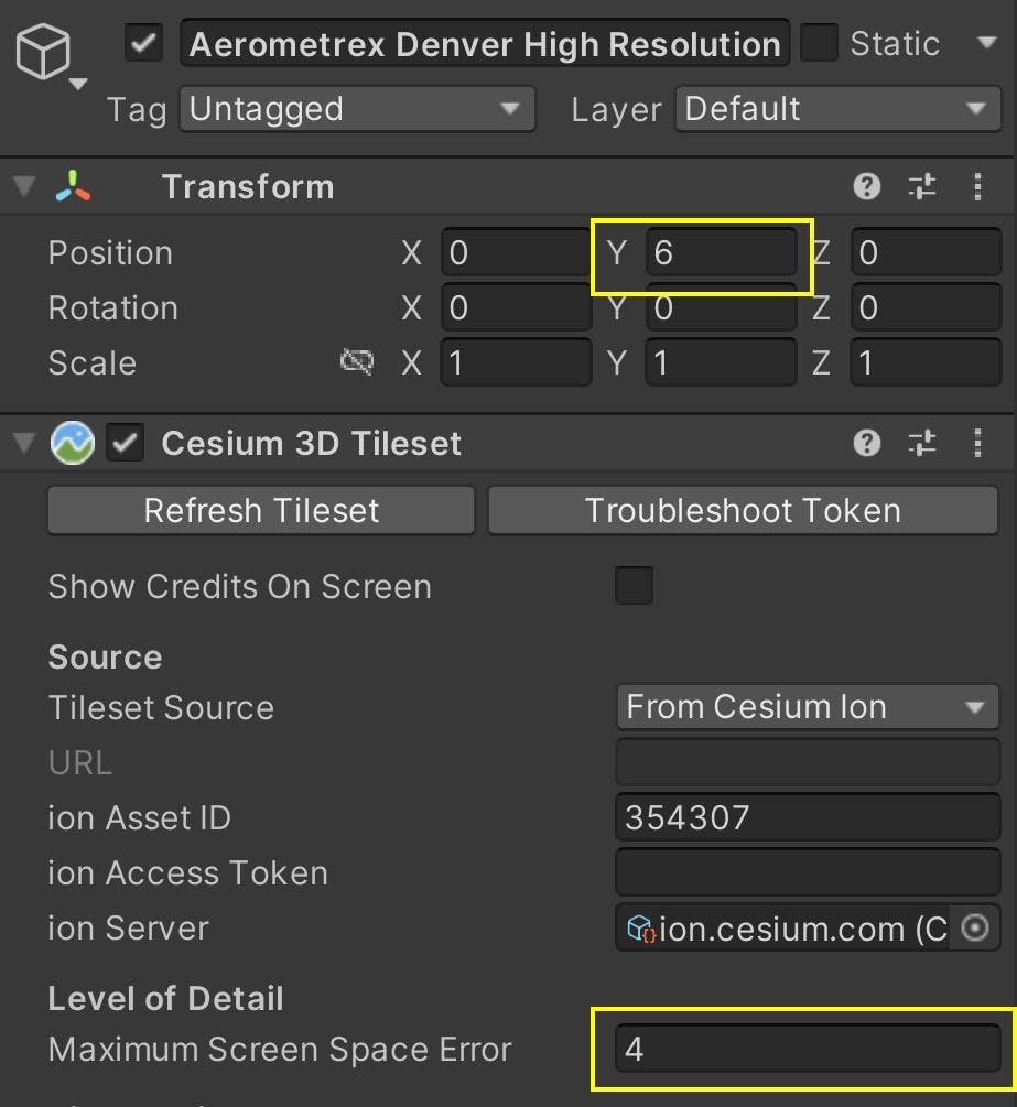
7Select the Aerometrex Denver dataset in the Hierarchy. In the Inspector, set the Y value of its Position to 6 so that it does not intersect with Cesium World Terrain. Then, set its Maximum Screen Space Error to 4 to encourage higher levels of detail to load.
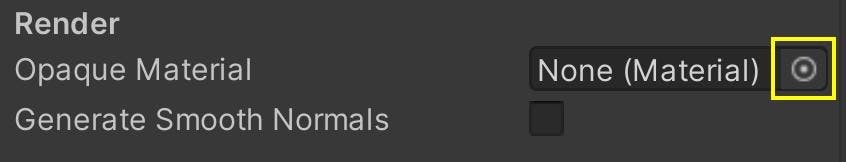
8With Aerometrex Denver still selected, find the Opaque Material property under the Cesium3DTileset in the Inspector. Click on the circular icon to the right of the “None (Material)” text.
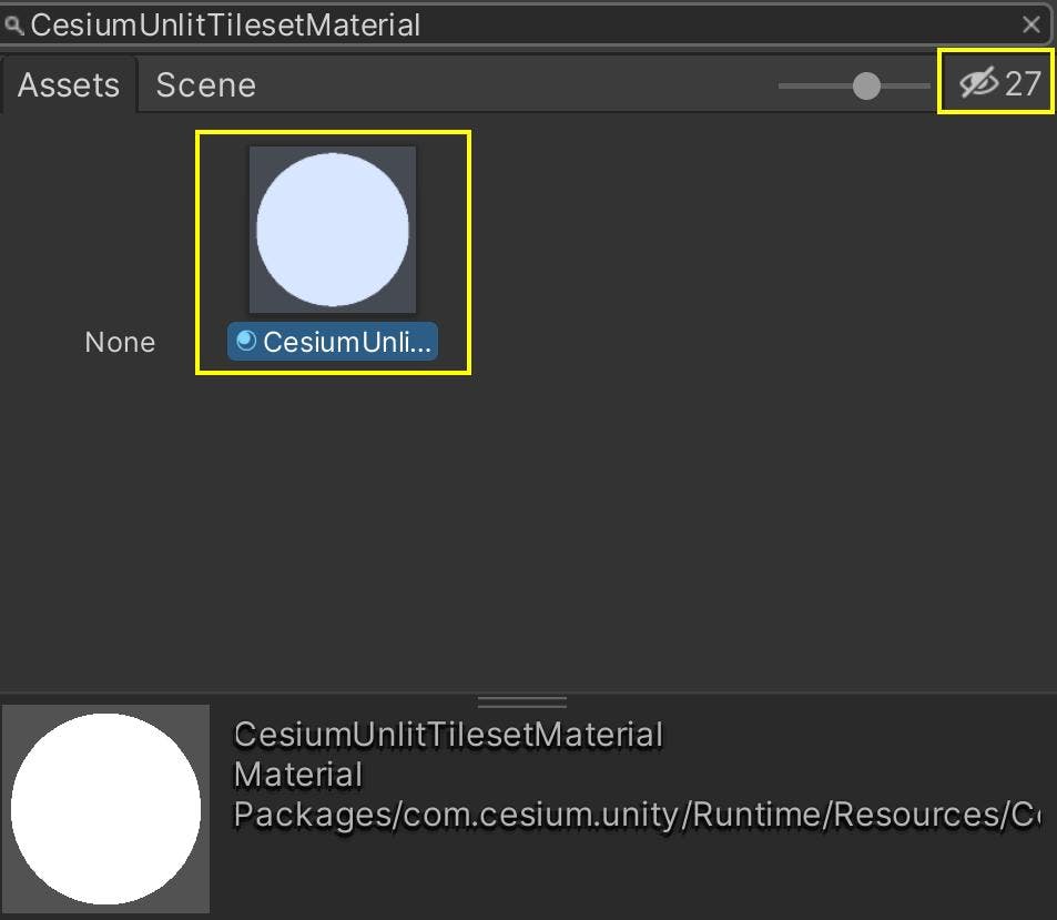
In the window that appears, search for the CesiumUnlitTilesetMaterial that comes with the plugin. If you can’t find this material, check that you have package visibility toggled in the top-right corner of the window.
This step of changing the tileset material is not mandatory for polygon clipping in your own applications. It is only suggested in this tutorial to increase visual clarity for the Aerometrex Denver dataset specifically. By assigning this material, the tileset will render without accounting for the sun, which will remove potential distractions from shadows or glares as you fit the polygon spline around the photogrammetry.
Now that your environment is ready, read on to learn how to create and reshape cartographic polygons.
The CesiumCartographicPolygon component represents a polygon that is fixed to a cartographic location on the globe. It uses a Spline component to define the polygon’s shape and a CesiumGlobeAnchor to geolocate itself in the scene. This means you can edit the Spline’s shape and Transform in Unity coordinates, while maintaining its globe-relative position with Cesium for Unity.
1In the Quick Add panel, click the “+” button next to Cesium Cartographic Polygon to add a new polygon to the scene. The polygon will generate a default spline for you so that you won’t have to build one from scratch.
The default square spline for CesiumCartographicPolygon.
Although Unity allows multiple splines to be defined on a single Spline component, CesiumCartographicPolygon only supports one polygonal spline. If the component contains multiple splines, then the first one in the list will be used.
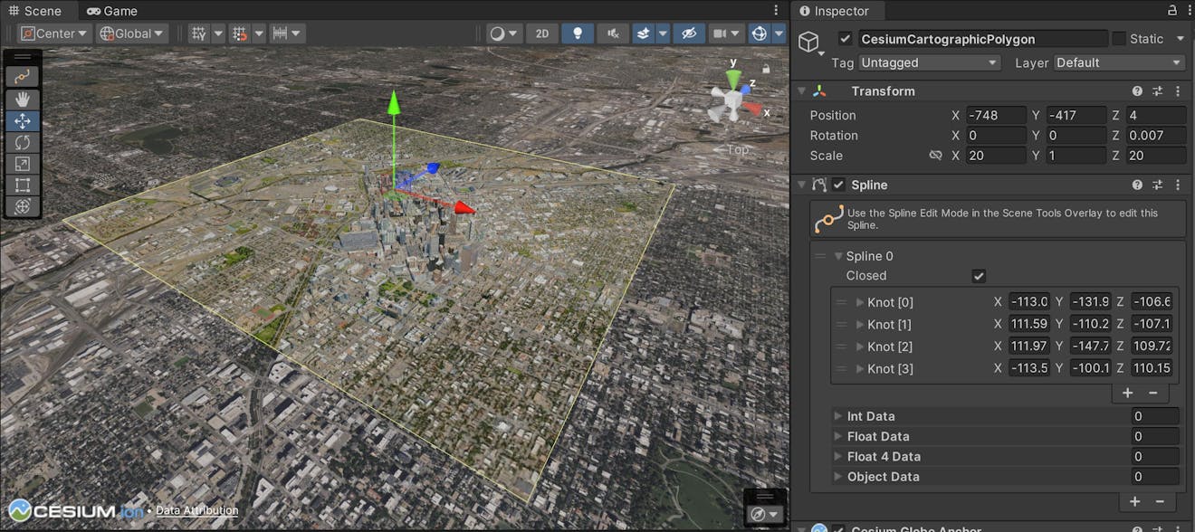
2Use the game object’s Transform to move and resize the polygon, such that it fully covers Aerometrex Denver. To start, set the Scale to 20 in the X and Z values. Then, reposition the game object with the Move Tool to center the polygon within the dataset.
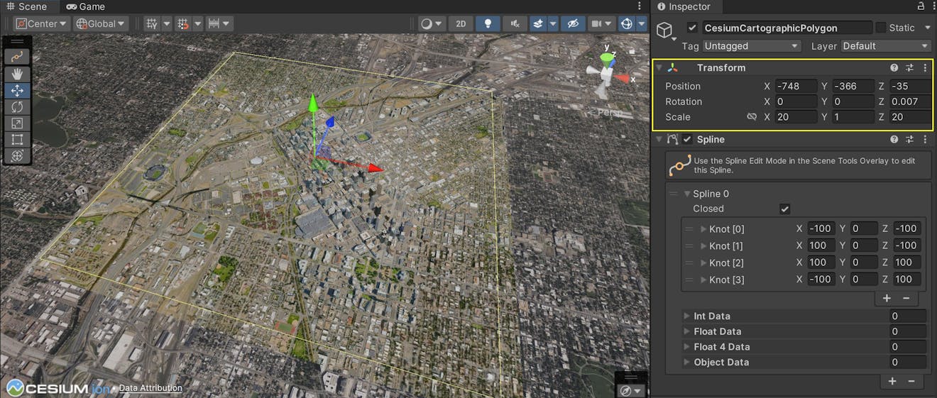
Example values for the CesiumCartographicPolygon after it has been scaled and moved. You do not need to copy these values exactly.
You can use the Transform to apply large changes and decrease manual editing of knots in the spline. Your polygon may not be aligned perfectly with Aerometrex Denver (yet), but you have set it up for the finer edits that you’ll make in the next step.
3Click on the Spline icon in the Scene View toolbar. If you can’t see it, make sure that your CesiumCartographicPolygon is still selected in the Hierarchy.
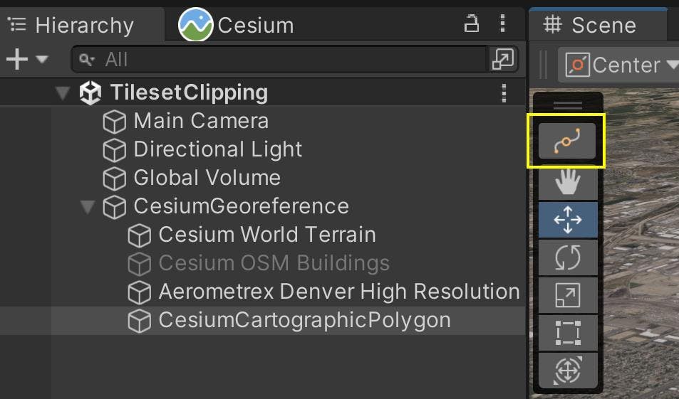
This button activates the mode for editing splines within Scene View. You can move, rotate, and scale points on the Spline using the same Move, Rotate, and Scale tools you would otherwise use in the Scene View toolbar. Each knot is represented by a clickable blue arrow that you can manipulate to reshape the spline.
Move knots by selecting them and using the Move tool as you would for any other Unity game object.
You can also add or remove knots in the spline by using the “+” and “-” buttons respectively under the list of knots in the Spline component.
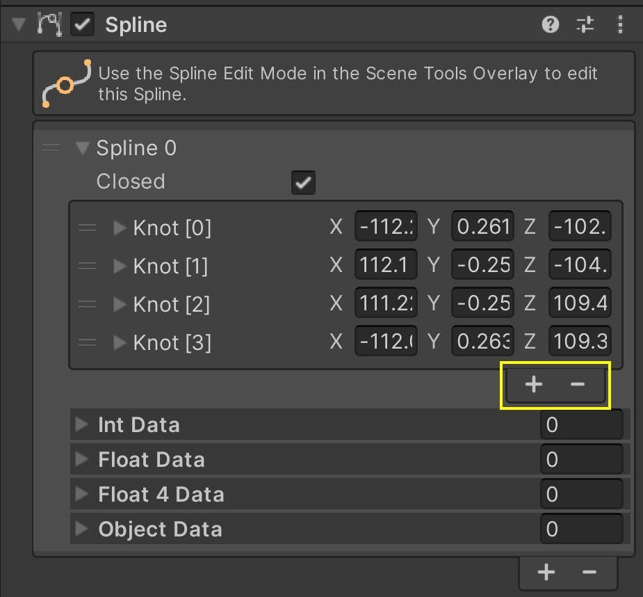
Ultimately, there must be at least three knots in your spline. The Spline must also be Closed, with all knots set to Linear. You can set these values in the Inspector and the Spline context tool, respectively.
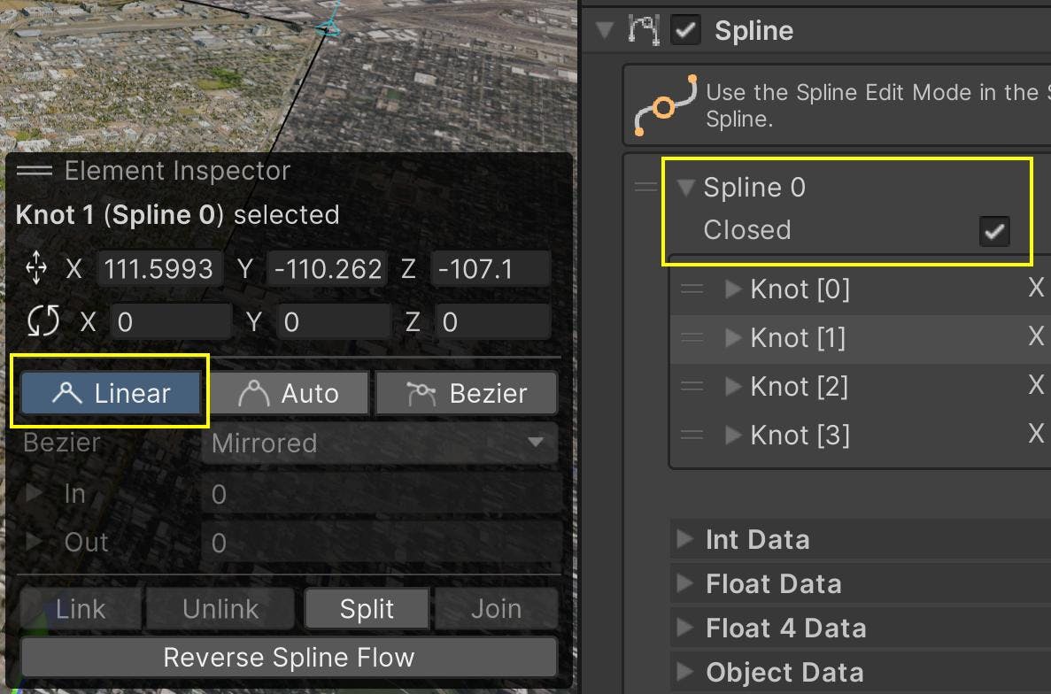
Curved splines are currently not supported, as they require different and potentially slower methods of rasterization.
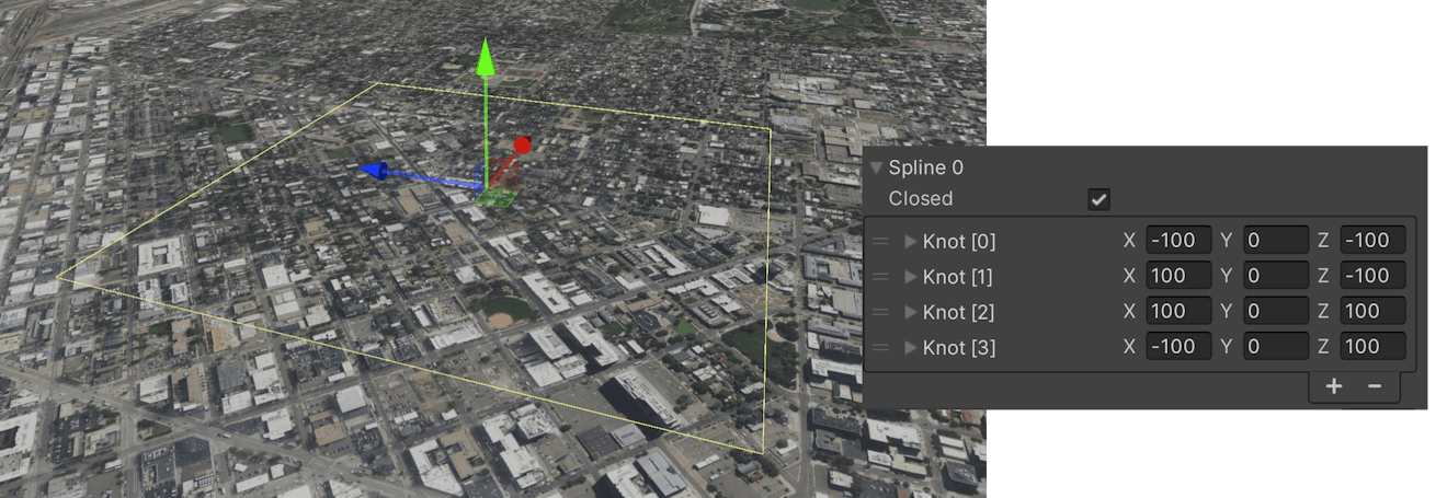
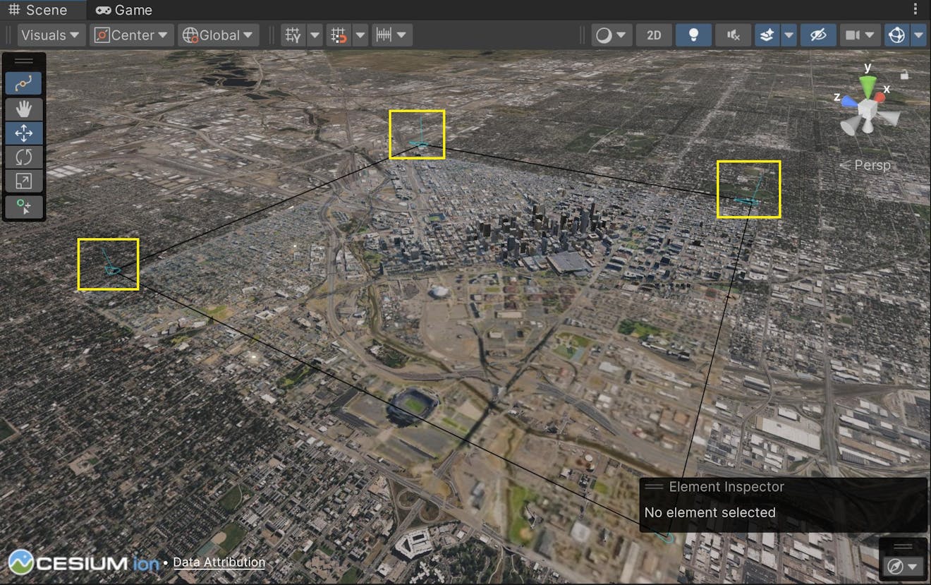
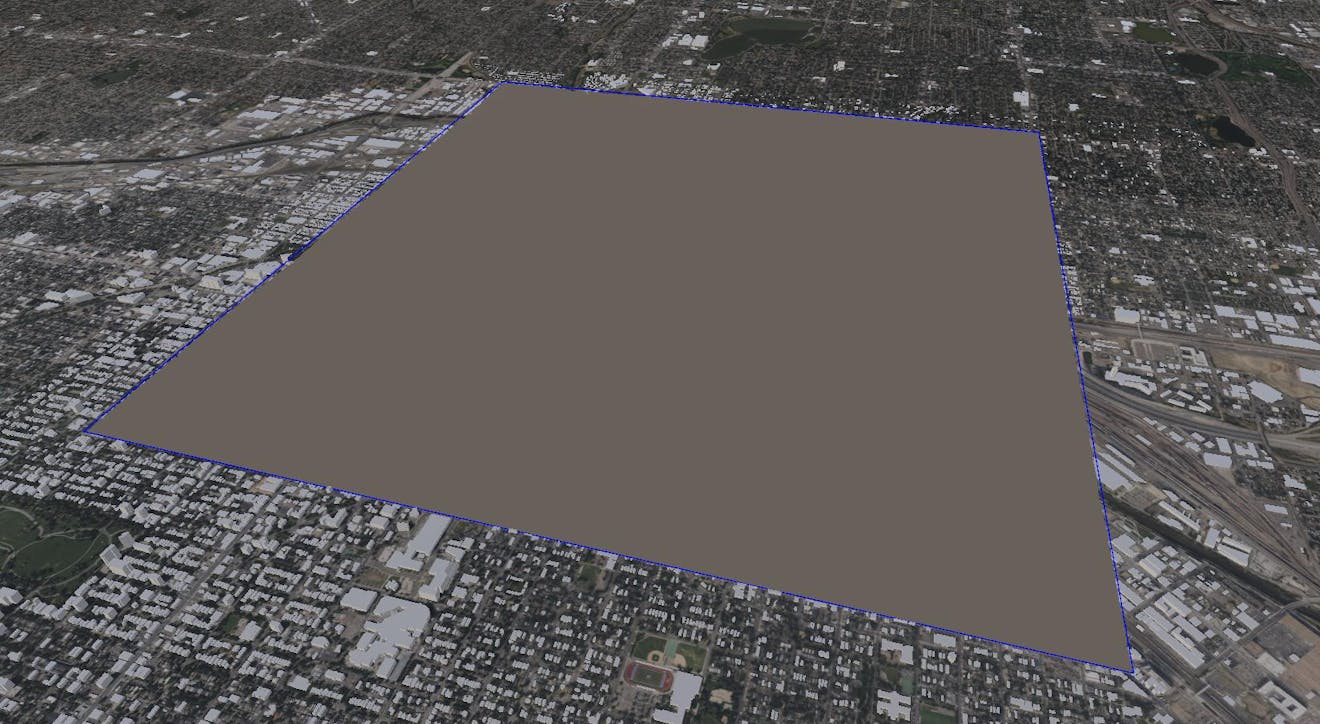
Once you’re familiar with the spline-editing tools, reshape the spline so it fits the edges of the Aerometrex Denver dataset. You can use the image below as reference for the positions of your spline knots. When you’re satisfied with your polygon’s spline, move on to the next step to learn how to use it for tileset clipping.
Your CesiumCartographicPolygon should closely fit the bounds of Aerometrex Denver after the previous section. Now, you will use the polygonal area to hide the portions of Cesium OSM Buildings that fall inside it. This prevents the buildings from covering the higher resolution Denver photogrammetry, while still rendering them outside to visually blend the two datasets.
By themselves, CesiumCartographicPolygons are simply shapes that are geolocated in the Unity scene. They must be explicitly assigned to a Cesium3DTileset before they can affect the tileset’s appearance. The CesiumPolygonRasterOverlay component establishes this link for you. When attached to a Cesium3DTileset, the overlay projects the polygons into rasterized textures, which are then used as masks in the tileset’s materials.
1Re-enable the Cesium OSM Buildings game object by selecting it and checking the box next to its name.
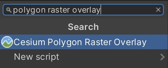
2With Cesium OSM Buildings still selected, add a new CesiumPolygonRasterOverlay component to the tileset using the Inspector. You can do this by clicking Add Component and searching for Cesium Polygon Raster Overlay, then selecting it from the list.
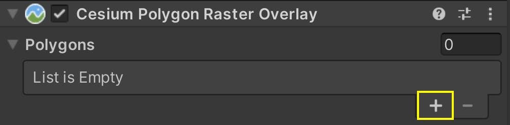
3Locate the list of Polygons under the CesiumPolygonRasterOverlay and click the “+” button to add a new element to the list.
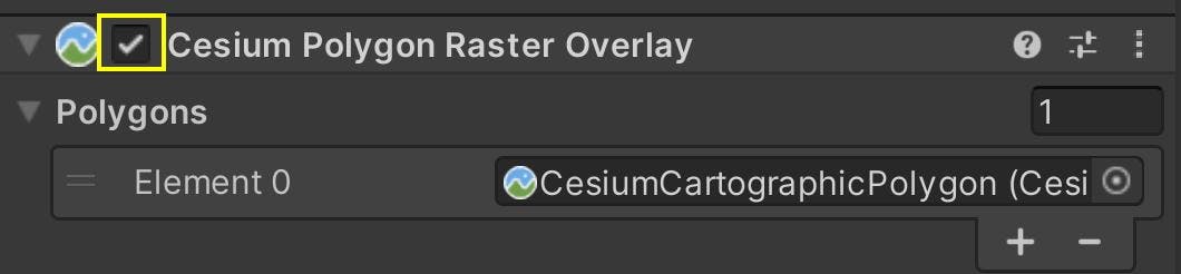
4The new element will appear with a text field, which displays the name of the CesiumCartographicPolygon it refers to. Since it is new, the text will say “None (Cesium Cartographic Polygon)” because it does not yet refer to a polygon in the scene.
To change this, click the circular icon to the right of the text field. This opens a popup window that lists all of the CesiumCartographicPolygon instances in the scene. Select the polygon that you shaped around the Aerometrex Denver tileset in the previous step.

Once assigned, the tileset will update automatically, and all of the OSM buildings inside the CesiumCartographicPolygon’s area will be hidden away.
Aerometrex Denver photogrammetry with Cesium OSM Buildings in the background.
You can still make changes to the CesiumCartographicPolygon, e.g., editing or repositioning the spline, if you’d like. However, CesiumPolygonRasterOverlay will not detect these changes automatically. You must manually refresh the CesiumPolygonRasterOverlay by disabling and re-enabling the component to make the changes apply.
Use the checkbox next to Cesium Polygon Raster Overlay to disable and re-enable the component. You can also refresh the component at runtime using a C# script.
You can also use multiple CesiumCartographicPolygons simultaneously by adding them under the list of Polygons in CesiumPolygonRasterOverlay.
5Besides OSM Buildings, the Aerometrex Denver tileset also overlaps with a region of Cesium World Terrain. Fortunately, the same CesiumCartographicPolygon can be used to apply clipping to multiple tilesets.
First, if you previously moved the Aerometrex Denver dataset, restore its Position to zero for all values.
Then, repeat the previous step for Cesium World Terrain. It should have a CesiumPolygonRasterOverlay component that contains a reference to your CesiumCartographicPolygon. Though the visual difference may be subtle, you can verify that it works by disabling Aerometrex Denver to expose the hole in the terrain.
By completing this step, you have blended three tilesets in one Unity scene and preserved visual quality by hiding their overlaps. Take advantage of cartographic polygons as you fuse different data sources and 3D assets in your own applications!
- CesiumCartographicPolygon operates in a 2.5-dimensional manner. The polygon is projected on the globe, and the projected area is used as a mask for clipping. This mask is used to clip everything below and above the knots in a spline.
- Because of the above, CesiumCartographicPolygon will not work for use cases that involve 3D clipping, e.g., cutting out windows on the side of a building. The height of a knot does not matter; only, its position translated into longitude and latitude coordinates.
- For the most accuracy in placing your polygon, it is best to position the knots of a spline as close as possible to the tileset’s surface.
There are two additional properties on CesiumPolygonRasterOverlay that may be useful as you use tileset clipping in your own applications.
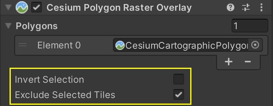
Invert Selection toggles whether to invert the areas defined by the polygons. In other words,
- When Invert Selection is false, then the areas inside the polygons are rasterized, and therefore clipped. They will appear to cut holes inside the tileset.
- When Invert Selection is true, then the area outside the polygons is rasterized, and therefore clipped. This will hide everything in the tileset except for the areas inside the polygons.
One use case for setting Invert Selection to true is if you wanted to show only a small portion of a dataset. For example, if you want to use Photorealistic 3D Tiles from Google Maps Platform for high detail visualization, but only in certain cities. You can use CesiumCartographicPolygons with Invert Selection set to true to isolate those regions of Photorealistic 3D Tiles.
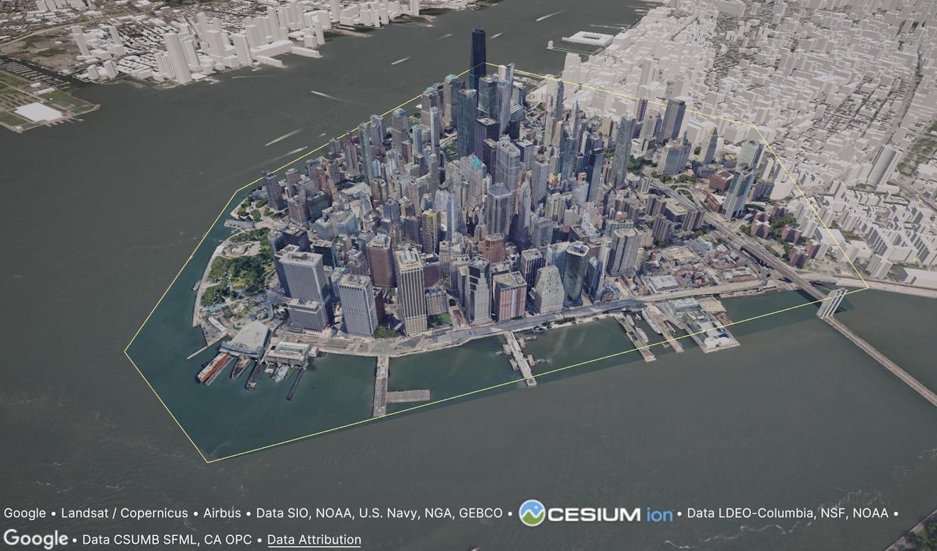
New York City, NY, USA visualized with Google Photorealistic 3D Tiles combined with Cesium OSM Buildings and Cesium World Terrain. A section of Photorealistic 3D Tiles has been isolated using a CesiumCartographicPolygon.
The other setting, Exclude Selected Tiles, controls whether tiles in the selected area are excluded from loading. In other words, this setting will prevent tiles from loading if they are completely inside a polygon (assuming Invert Selection is false). If you use CesiumCartographicPolygon for clipping, this setting acts as an optimization to avoid unnecessary processing of hidden data. However, if you use CesiumCartographicPolygon for non-clipping effects, such as highlighting the contents with a bright color, then be sure to disable this setting so that the tiles still load.
Exclude Selected Tiles is compatible with Invert Selection: when true, the tiles completely outside the polygon will be excluded. Tiles that lie both inside and outside of the selected area will be loaded, but any parts that fall in the selected area will be hidden by the clipping effect.
If you have questions about polygon clipping or its possible uses, visit the community forum and start a thread. We’d love to see you there!
What are you creating with Cesium for Unity? Share your work with us on X by tweeting @CesiumJS.