Placing Objects on the Globe
Having created a Level and imported some real-world assets like Cesium World Terrain or a photogrammetry model of a city, the next thing you will likely want to do is add some other objects from the standard Unity toolbox: meshes, foliage, characters, and many, many more.
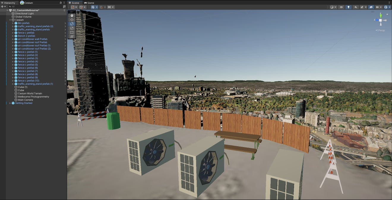
A rooftop in Melbourne with hand-placed, globally-anchored assets.
In this tutorial, you will:
- Add some simple Unity objects to a level.
- Learn in more detail how Cesium for Unity integrates into the Unity engine, which will help you avoid surprises as you build your levels.
- You have a world created with Cesium for Unity, perhaps created by following the Quickstart and Adding Datasets tutorials. Now you want to add some more Unity objects to it.
Adding objects near the origin of the CesiumGeoreference component is the same as adding them to any other Unity scene.
- If the Editor camera is not reasonably near (within a few kilometers of) the origin already, click the CesiumGeoreference component in the Hierarchy window. Then, click Place Origin Here in the Inspector window. You may also want to reset the location of the Main Camera to (0, 0, 0) so that play mode starts in the same place.
- Click the “+” icon at the top of the Hierarchy window and look for simple 3D objects to add to the scene.
- Drag a 3D object, such as a Cube, into the level Scene View.
- Use the transform gizmo controls in the Scene View to move, rotate, and scale the 3D object as desired.
Any normal Unity object can be added to the scene in the usual way. However, such a scene will only be accurate in a local area of a few kilometers. To build truly accurate, global-scale experiences on the other hand, Cesium for Unity introduces a feature called origin shifting. The rest of this tutorial gives an overview of the feature and describes how to use it.
Unity uses single-precision floating point coordinates to represent the positions and orientations of game objects. While this representation is sufficient for typical games built in Unity, it is insufficient to represent accurate vertex positions on a global scale. The precision of rendering, physics, and other Unity systems will only be accurate within several kilometers of the Unity origin.
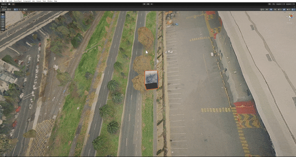
In this image, the camera is observing a cube that is located very far from the origin. The camera and the cube both exhibit “jitter,” jumping around with small camera motion.
Origin shifting is a Cesium for Unity feature that helps preserve vertex precision in very large worlds. It works by maintaining and updating a double-precision transform that represents the Unity coordinate system with respect to an Earth-centric coordinate system. The origin shifting system also maintains double-precision global coordinates for each georeferenced object in the scene.
When origin shifting is enabled in Cesium for Unity, vertex position accuracy is maintained across the globe by “shifting” the Unity origin location with the camera. As the camera moves across large distances, the Unity origin will “follow” it, thereby maintaining vertex precision near the camera at all times.
The consequence of “shifting” the Unity coordinate system is that all object transforms that were relative to the old coordinate system will become invalid. By default, this will cause objects to get misplaced in the world. The below sections discuss how to register custom game objects with the origin rebasing system so they get correctly updated on origin changes.
Automatic origin shifting can be enabled by adding the CesiumOriginShift component to the main camera. A CesiumGlobeAnchor component will automatically get added to the camera as well, this will help keep the camera upright with respect to the globe as the camera moves across the horizon.
The camera should be parented by a game object containing a CesiumGeoreference component. Recall from the Quickstart tutorial how adding a Cesium3DTileset also created a CesiumGeoreference in the Hierarchy window. The new Cesium3DTileset was automatically parented by the CesiumGeoreference game object. This is how tilesets maintain their globally accurate positions; any other georeferenced game objects in the scene should do the same.
During play mode, the CesiumOriginShift will cause the origin to repeatedly be shifted to remain near the camera. There should be no more jittering visible from the camera, regardless of how far it moves! However, this will cause non-Cesium game objects to become misplaced every time the origin changes, because their transforms are defined with respect to the Unity origin. This displacement can be fixed by “anchoring” the game objects to the globe, as discussed below.
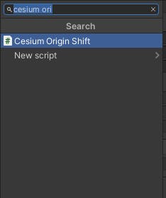
Click Add Component in the camera’s Inspector window and look for “Cesium Origin Shift”.
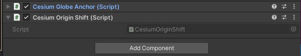
The CesiumGlobeAnchor component will automatically be added.
Now that origin shifting is enabled on the main camera, game objects in the scene need to be configured to handle origin shifting. This can be done by adding a CesiumGlobeAnchor component to each of the game objects. Like the main camera, any anchored game objects should be parented by the game object containing the CesiumGeoreference component in the scene.
Now, whenever the origin shifts to follow the camera in play mode, all anchored objects will handle the origin change correctly. The Unity coordinates of these game objects may be modified to account for the shifting, but they will not move with respect to the camera. This means that the origin shifting effects should not be discernible from the camera’s perspective.
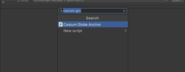
Click Add Component in the game object’s Inspector window and look for “Cesium Globe Anchor”.
Press Add Component in the game object’s Inspector window and look for “Cesium Globe Anchor”.
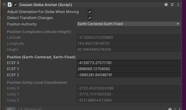
The CesiumGlobeAnchor will maintain the double-precision global coordinates for the parent game object.
The CesiumOriginShift component will not take effect in the Unity Editor. This is meant to prevent accidents where objects without CesiumGlobeAnchor are misplaced by unintentional origin shifts. Still, it is often useful to change the origin to a new location while in the Editor, in order to more conveniently edit assets in another location.
Before changing the origin, it is important to anchor all non-Cesium objects to the globe with the CesiumGlobeAnchor component. Otherwise they will lose their positions relative to the globe. Once all game objects are anchored, click on the CesiumGeoreference game object in the Hierarchy view to open its Inspector. If the Editor camera has already been moved to the desired new origin location in the Scene View, press the Place Origin Here button.
The Place Origin Here button on the CesiumGeoreference can fix the Editor camera's orientation with respect to the globe whenever the Editor strays far from the original origin.
Alternatively, you can change the Longitude, Latitude, and Height of the origin (relative to the WGS84 ellipsoid) by changing the values in their respective fields. The origin can also be changed in terms of Earth Centered, Earth Fixed (ECEF) coordinates. Make sure to set the Origin Authority to Longitude Latitude Height or Earth Centered, Earth Fixed respectively.
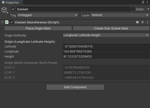
In the editor, the CesiumGeoreference's origin can be changed with the Longitude Latitude Height or Earth Centered, Earth Fixed fields, or with the Place Origin Here button.
- Even with world origin shifting, faraway objects have large Unity coordinate values and will be represented less precisely within the engine. However, this imprecision will not be problematic for those faraway objects, because small errors in vertex position will correspond to less than a pixel.
Note that the precision of Unity game object coordinates is restored when the camera moves back toward a previously faraway object. This is made possible by the origin shifting system, which maintains a double-precision global transform for each globe-anchored game object. For each origin shift, the underlying global coordinates are used to recompute Unity coordinates for each anchored game object.
World origin shifting fulfills an important purpose, but it has two downsides:
- There is some performance cost in frequently updating the position of every object in the level when the origin changes.
- Some Unity objects may not behave well with origin shifting. For example, Unity systems like physics solvers and global illumination may internally cache positions with respect to Unity’s origin. These positions will become invalid when the origin is shifted.
If you expect the camera to stay near the origin in your application, or at least to not view objects up close while far from the origin, it may not be necessary to enable origin shifting at all.
- Earth is an ellipsoid. Unlike typical experiences built in Unity, Cesium for Unity takes place in a global context. Since the Earth is ellipsoidal, it is important to remember that different parts of the world have local reference frames with conflicting “up” directions. This could cause strange issues for any Unity system that makes assumptions about the reference frame. For example, gravity might be applied in the wrong direction, or globe-unaware cameras may appear upside down far away from the origin. If origin shifting is enabled, the local coordinate system near the main camera will always be intuitive in Unity (X-East, Y-Up, Z-North).
- Tile culling and LODs: In Cesium for Unity, Cesium3DTileset components stream massive datasets into your application in a view-dependent manner. These datasets are often large, containing terabytes of data. In order to stream tiles efficiently, Cesium for Unity uses two crucial techniques: hierarchical level-of-detail (HLOD) and culling.
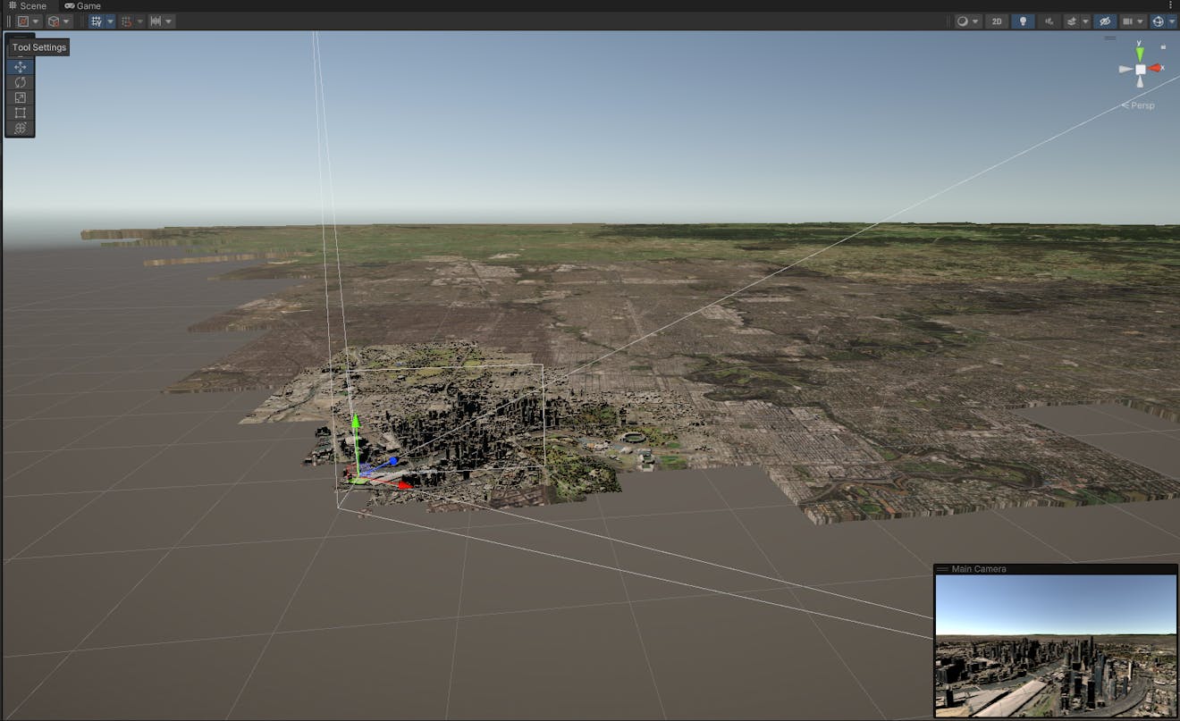
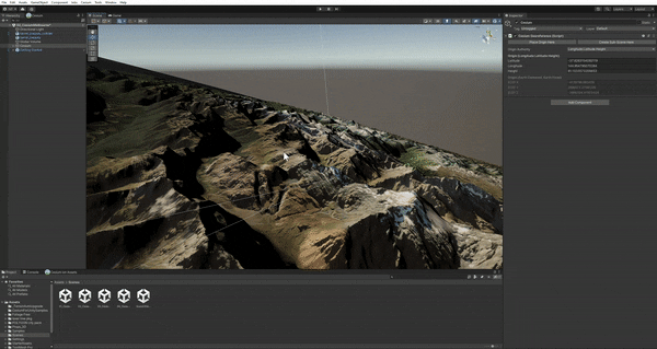
Tile culling is visualized here by viewing the Scene View camera while the main camera (bottom right) is in play mode. Notice how tiles outside the frustum are missing—they are being culled to prioritize the tiles in front of the camera.
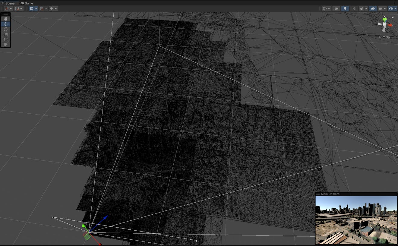
Hierarchical Level-of-Detail (HLOD) is visualized here by looking at the tileset’s wireframe. Again, the main camera frustum can be seen from a third-person perspective—notice how the triangle density decreases as a function of distance from the camera. Cesium for Unity loads higher detail up-close to the camera and lower detail further away.
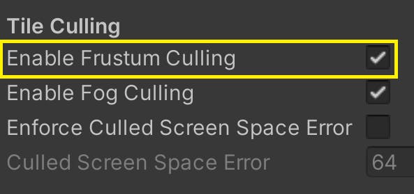
While these techniques are used to streamline the number of tiles required to render a scene from the current view, they can cause unexpected behavior for objects further from the camera. For example, physically simulated objects resting against a 3D tileset may fall through the ground if the camera looks away, since tiles that are not visible to the camera are culled. You can disable this culling if you view the Cesium3DTileset component in the Inspector and uncheck Enable Frustum Culling.
However, even without frustum culling, tiles will still change based on their requested level of detail. As the camera moves through the scene, tiles will present more or less detail to the user, which involves changes to their meshes and colliders. This can cause physical objects to fall through the ground or be shot into the air by the changing tiles.
To avoid surprises, remember that tile collision is only meant to be used for camera-based raycasting and simple camera collision (to prevent the camera clipping through the ground). For more complicated physics simulations, it is recommended to place persistent proxy colliders and to not rely on the tile collision meshes. Collision meshes for 3D Tiles can be disabled by unchecking Create Physics Meshes in the Inspector window for Cesium3DTilesets.