Transition Between Locations on the Globe
In this tutorial, you will learn to smoothly fly between two locations on the Cesium for Unreal globe using Unreal Engine Blueprints.
This tutorial is for Cesium for Unreal version 1, which is now obsolete. Please see the updated version for Cesium for Unreal v2.
A transition between Sydney and Melbourne, Australia.
You’ll learn how to:
- Work with cartographic coordinates in Unreal Engine
- Use Cesium's DynamicPawn and Blueprint to smoothly fly between locations on the globe
- Customize DynamicPawn's Fly To functionality with curves
- Create viewpoints to mark locations and anchor them to the globe
Blueprints is the visual scripting system inside of Unreal Engine based on the concept of a node-based interface. Although it helps to have some knowledge of coding, Blueprints make it easier for non-programmers to add logic to their application.
- Know how to set up a basic Cesium for Unreal application. Check out our Cesium for Unreal Quickstart guide for instructions on starting with the Cesium for Unreal plugin.
Start with the 01_CesiumWorld level in the Cesium for Unreal Samples, or create a new level following the instructions in the Quickstart.
1Select the CesiumGeoreference actor in the World Outliner.
In the Details panel, look for the Origin Latitude, Origin Longitude, and Origin Height parameters. Set them to the values of the source location. For example, to start in Sydney, Australia, we can type in the following coordinates:
Origin Latitude = -33.871799
Origin Longitude = 151.206696
Origin Height = 3000.0
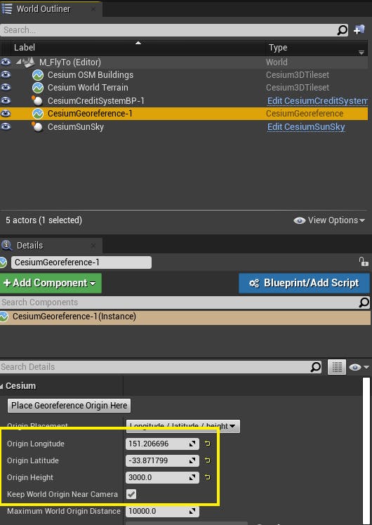
2Enable Keep World Origin Near Camera under the origin parameters, which will ensure we maintain the correct orientation throughout the flight.
1If you do not currently have a DynamicPawn in the scene, you'll need to add one. Use the Cesium panel to add a DynamicPawn. To focus on the pawn, double-click its label in the World Outliner.
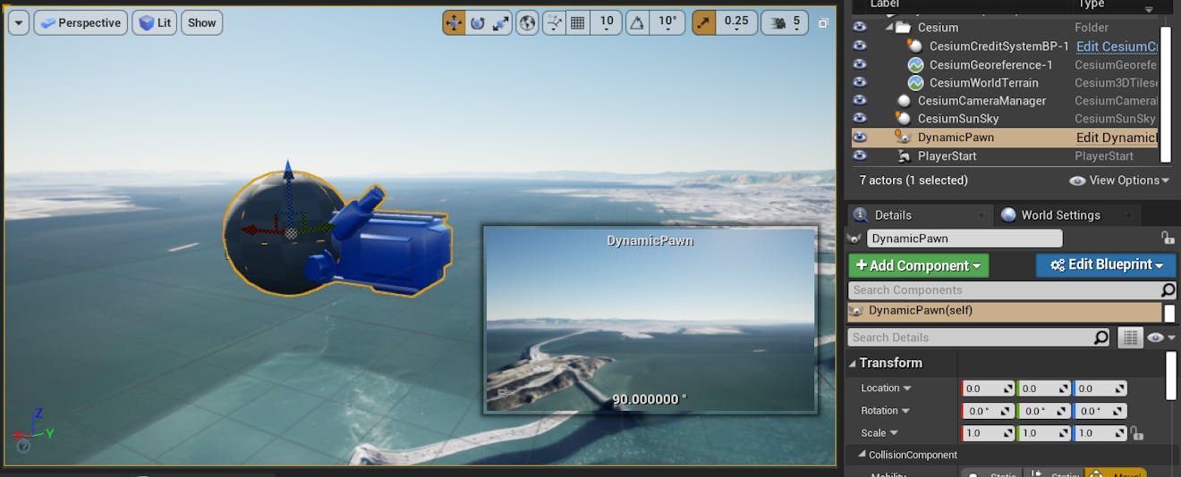
2Frame your starting view by adjusting the position and rotation of the DynamicPawn using the translation and rotation gizmos. Since the pawn has a camera attached to it, you'll see a preview of the scene from the DynamicPawn's view in the bottom right corner of the editor.
3In the Details panel, search for “possess”. Select the dropdown next to Auto Possess Player and select Player 0.
Now in Play mode, you will be able to control the DynamicPawn with the mouse and WASD keys.
A Player is the entity that you will control in Play mode. You can move around the scene and perform other tasks using the Player. You can also switch between different Players if there are multiple ones in the scene.
In this step, you are going to create a Blueprint function that allows you to press a key on your keyboard and trigger a flight between two locations on the globe.
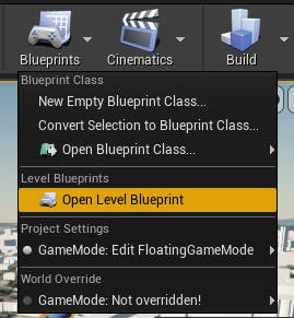
1Open the Level Blueprint by going to Blueprints -> Open Level Blueprint at the top panel of the Unreal Engine editor.
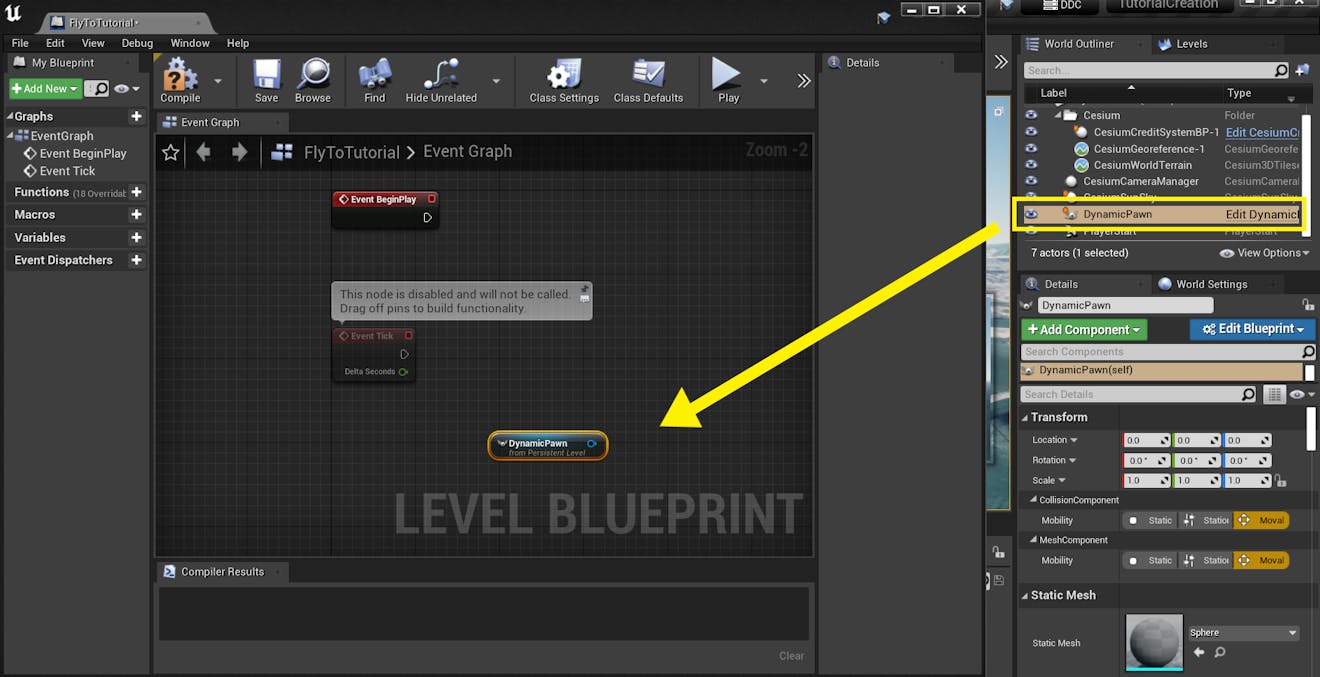
2From the World Outliner, select the DynamicPawn actor. Drag-and-drop the DynamicPawn into the Event Graph in the Level Blueprint.
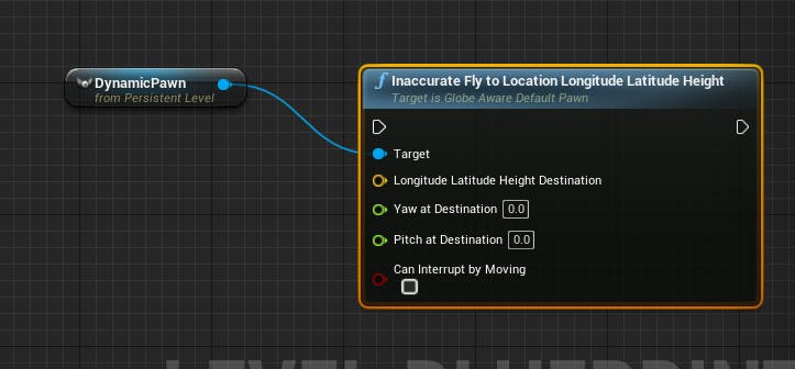
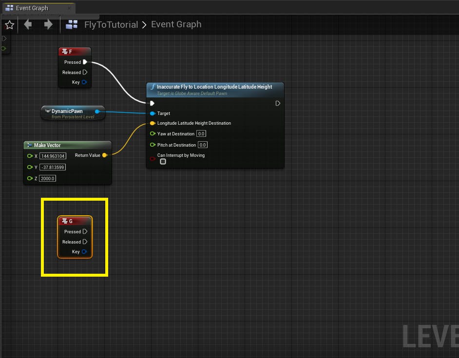
3Drag a connection from the DynamicPawn node. In the menu that appears, search for "fly" and select the Fly to Location Longitude Latitude Height function. If you are using Unreal Engine 4, the function will be named Inaccurate Fly to Location Longitude Latitude Height.

Q: Why is this function inaccurate in Unreal Engine 4?
In Unreal Engine 4, Blueprints do not support double precision. As a result, many Cesium functions available in Blueprints use single precision computations instead, which can cause inaccuracy of up to a meter or so. If you require fully accurate calculations for your application, you can use C++ to access double precision versions of inaccurate functions.
In Unreal Engine 5, Blueprints do support double precision. You can use Blueprint or C++ to access a fully accurate version of this function.
4If you are interested in how the function works, you can hover the mouse over the function node to read the documentation. One of the parameters of the function is Can Interrupt By Moving, which is the last pin on the function node. If you would like to be able to move the pawn mid-flight with the standard WASD movement keys, you can tick the checkbox next to this parameter.
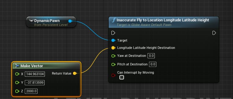
5Right-click on an empty space in the Event Graph and add a Make Vector node. Enter the values for the longitude, latitude, and height of the destination into the X, Y, and Z variables respectively. In this tutorial, we will fly to Melbourne, Australia, with longitude = 144.9631, latitude = -37.8136, and height = 2000.
6To trigger the transition, add a Keyboard Event and connect its output pin to the input pin of the Inaccurate Fly to Location Longitude Latitude Height node. The example below is using the F key.
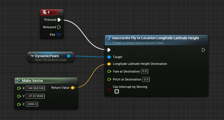
7Compile the newly added nodes with the Compile button at the top left corner of the editor.
To check whether you have set up everything correctly, head back to the main editor. Press Play at the top toolbar. The initial view should be the same view you saw earlier through the Dynamic Pawn’s camera preview. Press the F key (or whichever key you chose to use) on the keyboard to see the flight in action.
The camera will transition between Sydney and Melbourne very quickly. In the next step, you will set some variables to customize the speed and height of the DynamicPawn throughout the transition.
In this step, we will adjust some variables of the DynamicPawn actor to customize how the pawn transitions to the destination.
DynamicPawn's flight settings
In the DynamicPawn's Details panel, you'll see several parameters that impact the pawn's Fly To behavior.
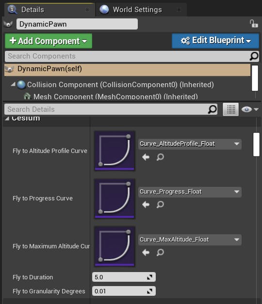
The Fly to Duration parameter determines how many seconds the flight will take from beginning to end. The higher the value, the slower the pawn will move.
The Fly to Granularity Degrees parameter determines the number of points used for the flight path interpolation. The default setting should be suitable for most use cases.
The Fly To Curves are UCurveFloat assets that are used in the Fly to Location function when computing the pawn's path from the source location to destination. Cesium for Unreal comes with preset curves that the DynamicPawn uses to fly between locations. Each curve is explained below, including the behaviors of the default curves.
Fly to Altitude Profile Curve
The Fly To Altitude Profile Curve controls how the pawn's altitude changes throughout the duration of the flight. The X axis represents the time during the flight. The Y axis represents the pawn's altitude, where 0 is the pawn's starting and ending altitude, and 1 is the maximum altitude (determined by the Fly To Maximum Altitude curve). This curve must be kept in the 0 to 1 range on both axes.
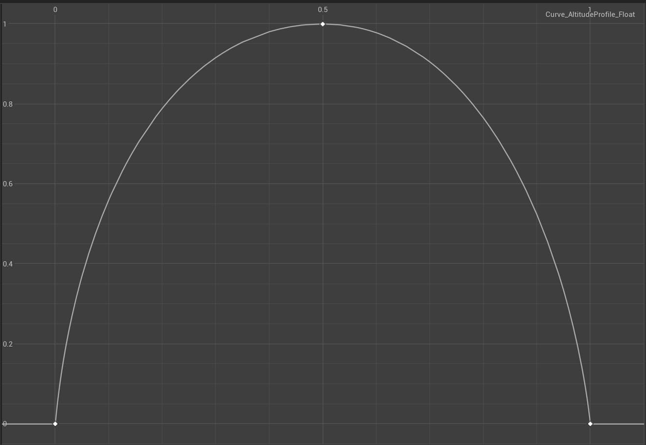
The default curve starts and ends at 0, which is recommended to make sure the transitions at the beginning and end of the flight are seamless. With the default curve, the pawn will spend most of the flight at higher altitudes.
Fly to Progress Curve
The Fly To Progress Curve controls the pawn's speed throughout the flight. The X axis represents the time during the flight. The Y axis represents the location along the flight path. This curve must be kept in the 0 to 1 range on both axes.
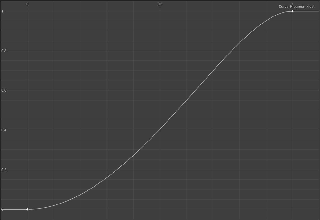
The default curve is s-shaped, so that the pawn will slow down at the beginning and end of the flight.
Fly to Maximum Altitude Curve
The Fly To Maximum Altitude Curve determines the relationship between the distance to travel and the maximum flight altitude. The X axis represents the distance between the start and end location, and the Y axis represents the maximum altitude. Distances in this graph are in meters. Feel free to adjust the maximum X and Y axes to suit your needs.
This curve ensures that the pawn will fly at a reasonable height for the distance that it is traveling. It might look odd if the pawn flew out to space in order to move ten kilometers.
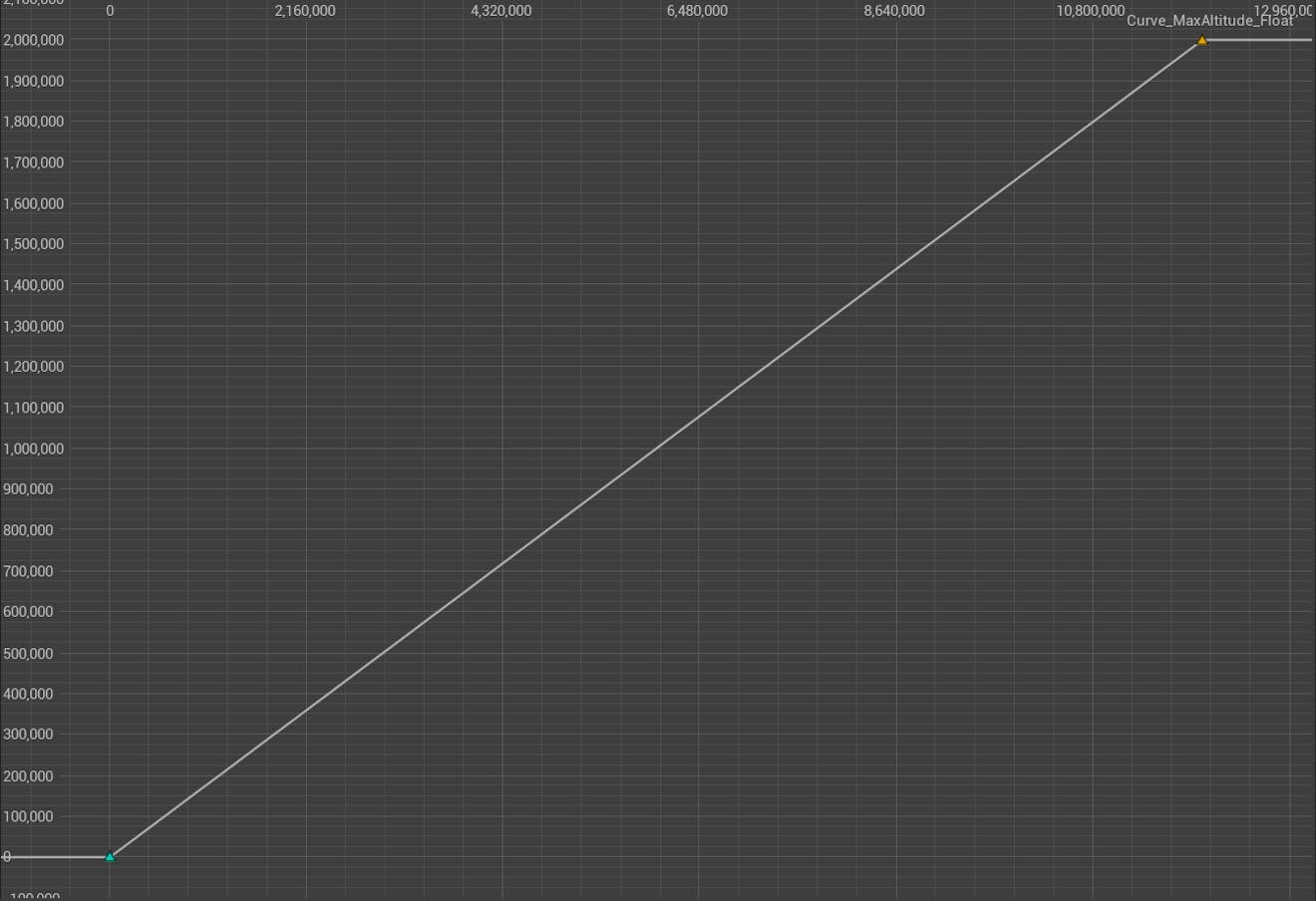
The default curve is linear. The maximum X value is 12000000 units/12000 kilometers. The maximum Y value is 2000000 units/2000 kilometers.
1Right-click in the Content Browser and create a new Curve asset (Miscellaneous -> Curve). A Pick Curve Class window will appear. Choose CurveFloat, then press the Select button to create the asset.
This curve will be used to replace the Fly to Altitude Profile Curve. Name your new curve "Curve_MyAltitudeProfile".
2Double-click on the curve in the Content Browser to open the Curve Editor window. Add three key points to the graph (Right click -> Add Key). Set the first point to (0,0). Set the second point to (0.5,1). Set the last point to (1,0).
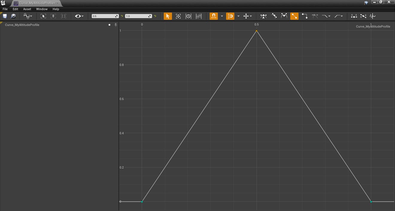
3Use the Curve Editor tools to create an interesting curve shape. The following tips may help you in creating your curve.
- You can set the exact coordinates of a point by clicking on the point, then using the text fields in the top bar of the curve editor.
- Different interpolation settings are available for the curve points on the right side of the top bar.
- Make sure your curve doesn't exceed the bounds between (0,0) and (1,1) on the graph.
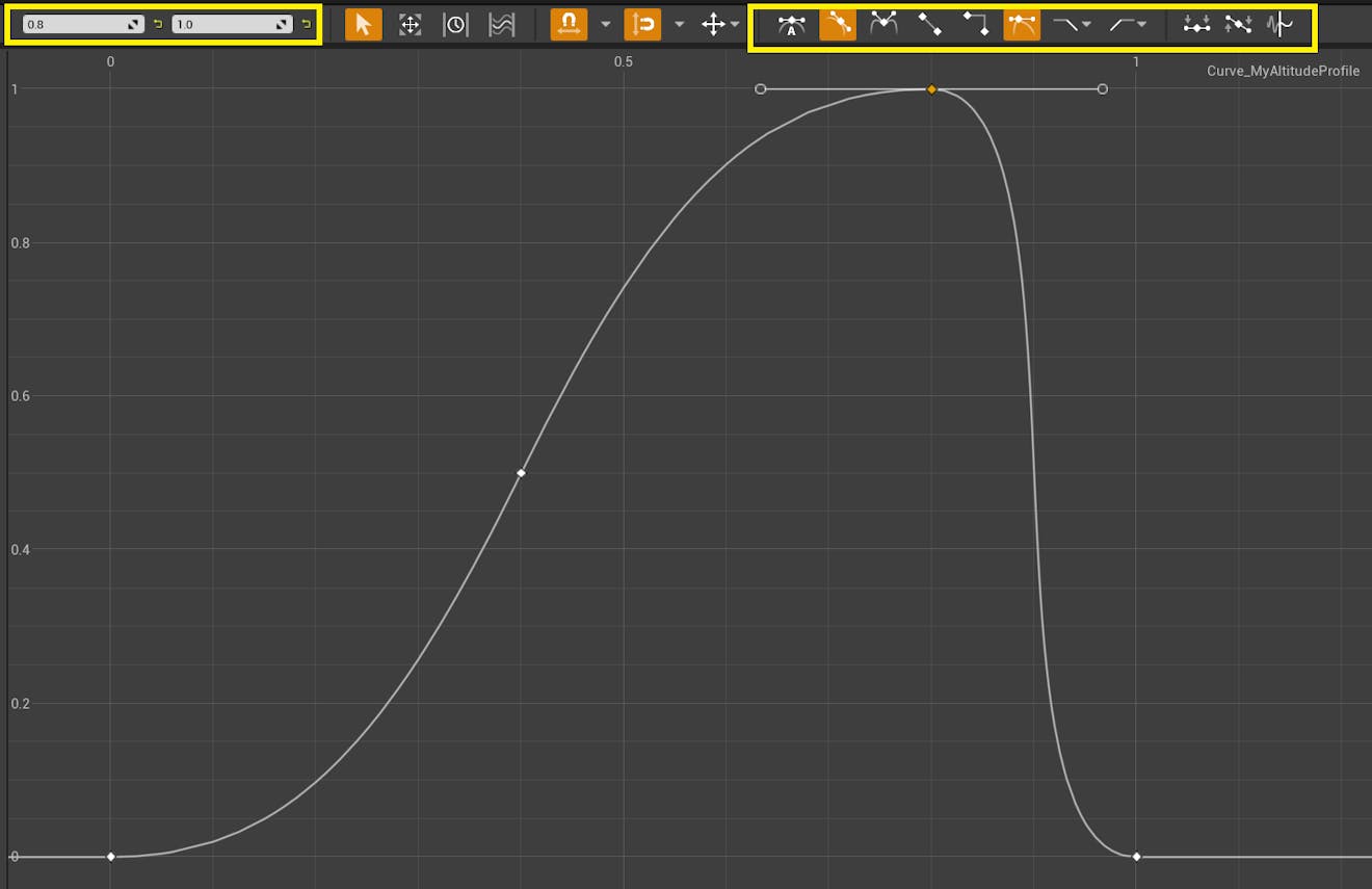
The example curve in this tutorial uses the cubic interpolation setting for each point to achieve a smooth line. Notice how it differs from the default Fly to Altitude Profile curve.
Once you've finished creating your curve, save the curve asset and close the Curve Editor window.
4In the Details panel, set the Dynamic Pawn's Fly to Maximum Altitude Curve to your new curve asset.
5Set the Fly to Duration parameter to 10 seconds.
6Save your level, then press Play. Press the F key again to activate the flight. Since you changed the Fly To Duration, the camera will move more slowly. The pawn's altitude will follow your custom curve.
7The next section will cover a different way of flying between locations. You may wish to reset DynamicPawn's settings back to default before continuing.
It’s not always convenient to type in starting and ending WGS84 coordinates to specify a flight. As an alternative, actors can be placed in a scene to serve as "geo-markers”. These markers can be placed at any geographic location, and their position can later be used as the Dynamic Pawn's flight destination.
Any actor on the globe can be used as a geo-marker. In this tutorial, you'll learn how to create a simple geo-marker using a cube and a Globe Anchor component.
1First, pick a location for your geo-marker. You can change the Georeference Origin to your new location, or fly there with the editor camera and press the Place Georeference Here button on the CesiumGeoreference actor. The geo-marker in this tutorial will be placed in Christchurch, New Zealand at latitude -43.539723, longitude 172.636686, and height 2000.
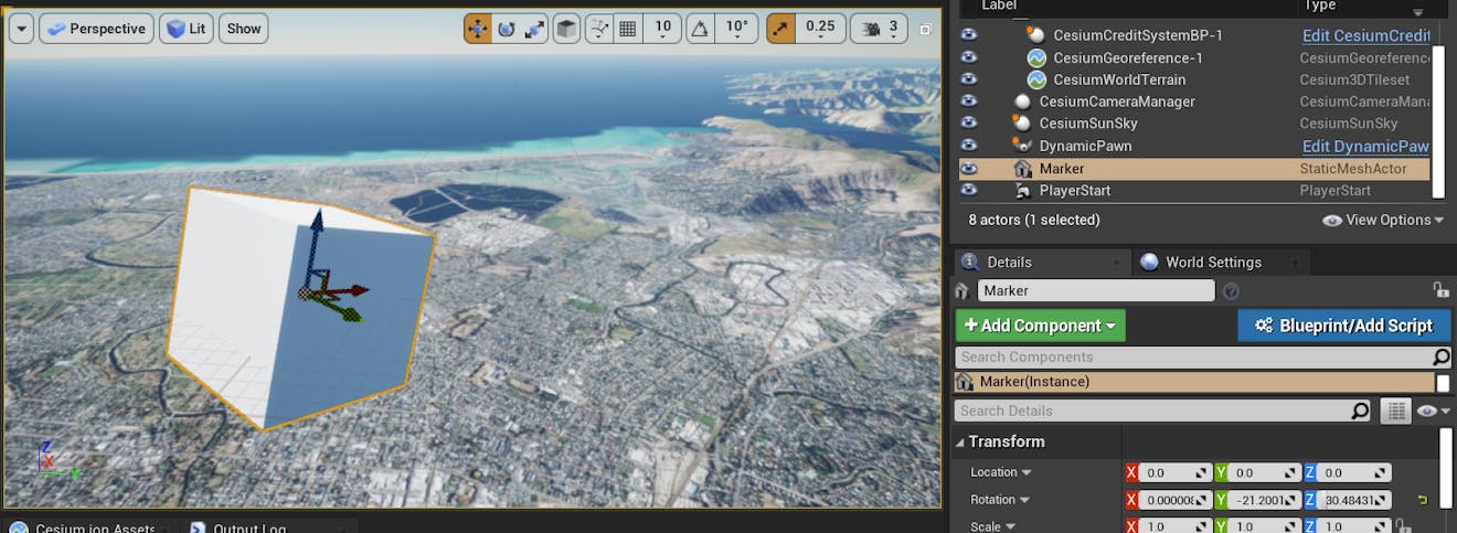
2Add a Cube to the scene from the Place Actors panel. Rename the cube to "Marker".
Rotate the cube to frame a view of the location. To set up the view more precisely, you can right-click on the cube and select Pilot actor to "see" through its perspective.
If you are using sublevels, make sure that the cube is added to the Persistent Level.
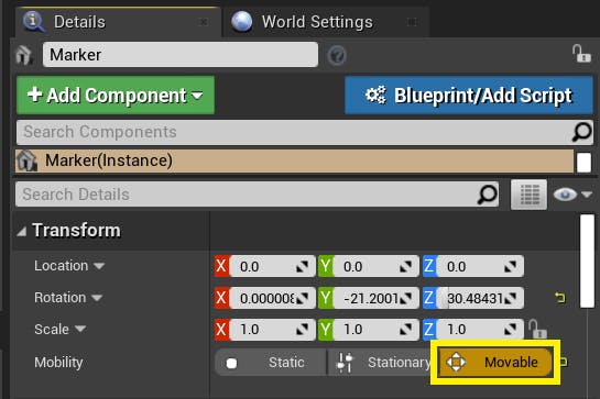
3Set the marker’s mobility to Movable.
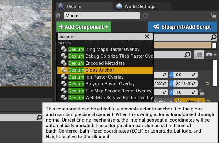
4Add a Cesium Globe Anchor component to the cube. This component will provide global context for this actor, and ensure it stays in the desired location even if the Georeference Origin changes. To read more about georeferencing in Cesium for Unreal, see Placing objects on the globe.
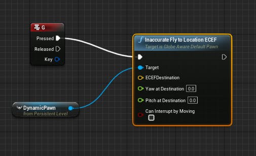
5Return to the Level Blueprint. In the Event Graph, add a new Keyboard Event event for the "G" key.
6As before, add a reference to the DynamicPawn. This time, drag off the DynamicPawn and create a Fly to Location ECEF* node.
The node will be named "Inaccurate Fly to Location ECEF" if you are using Unreal Engine 4.
Connect the execution pin from the “G” keyboard event to the Fly To Location ECEF function.
Fly to Location ECEF works just like Fly to Location Longitude Latitude Height, but it uses the ECEF (Earth-centered, Earth-fixed) coordinate system instead of the longitude/latitude/height geographic coordinate system. Cesium for Unreal includes functions for both of these coordinate systems. Feel free to use whichever coordinate system you prefer in your applications.
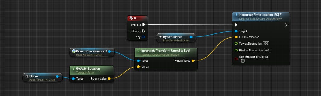
7Drag in the marker and the default CesiumGeoreference from the World Outliner into the Level Blueprint.
8Create a Get Actor Location node from the marker actor. Then, create a Transform Unreal to ECEF* node.
* If you are using Unreal Engine 4, the Transform Unreal to ECEF node will be named "Inaccurate Transform Unreal to ECEF".
Connect the output of the GetActorLocation node to the Unreal pin of the coordinate transformation node.
Finally, connect the result of the coordinate transformation node to the destination pin on the Fly to Location ECEF node. The node graph should resemble the image below.
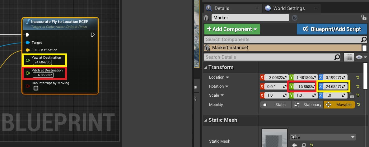
9Now, you'll set the view angle of the camera at the destination.
Set the Pitch at Destination input on the Fly to Location ECEF node to the Marker's Y rotation. Set the Yaw at Destination to the marker's Z rotation. Be sure not to include any symbols, like °.
10Save and compile the level blueprint. Hit Play and press G to try it out.
To be able to cancel an in-progress flight by moving the pawn manually, check the Can Interrupt By Moving box.
The DynamicPawn flies from Denver to Boston.
You have completed the Cesium for Unreal Getting Started tutorials, but there’s still a lot to learn about Cesium for Unreal.
Learn how to add a physics-based controller to levels with 3D Tilesets in the Using Custom Controllers tutorial.
Try the Build a Flight Tracker with Cesium for Unreal tutorial.
If you’re interested in building out your world, check out Using a Geospatially Accurate Sun, Lighting and Rendering Scenes, or Placing Foliage on Cesium Tilesets.