Visualize Per-Feature Metadata
This tutorial is for Cesium for Unreal version 1, which is now obsolete. Please see the updated version for Cesium for Unreal v2.
Per-feature metadata is a core component of 3D Tiles that helps users build rich, informational, and immersive experiences by enabling powerful feature-level semantics. You may need to know whether a certain part of a mesh should be glass or brick in order to apply the appropriate material. Or, perhaps you'd like to be able to pull up information about a building on the fly and display the address, number of rooms, and date of construction to your users. Information like this can be stored and accessed as per-feature metadata.
Per-feature metadata is semantic information about a tile that is embedded in the tile itself. It is stored in the tile content along with geometry and texture information to optimize look up and styling during runtime. Cesium for Unreal can read per-feature metadata from tiles with the EXT_feature_metadata glTF extension or from 3D Tiles with a B3DM batch table or batch table hierarchy.
A "feature" is a distinguishable part of an overall model, such as a single building in a model of a city. Cesium for Unreal is currently built around the EXT_feature_metadata extension, which uses the term "metadata" to describe the properties that are associated with individual features. In a future version, Cesium for Unreal will move to the newer EXT_mesh_features extension, which uses the more accurate term "per-feature data".
This tutorial outlines the basic steps to visualize per-feature metadata by material styling and printing feature properties on screen. The steps outlined below use a tileset of 3D buildings in New York City, which is available to all Cesium ion users via the Asset Depot. If you have your own tileset with compatible per-feature metadata, you can use that as well, though property names may be different.
If you'd like to learn more about using per-feature metadata in Unreal, check out the Per-Feature Metadata Technical Reference.
You’ll learn how to:
- Use the CesiumEncodedMetadata component to generate material layers and style a tileset with per-feature metadata
- Access per-feature metadata of a tileset with Blueprint
- Select features in play to view associated metadata properties
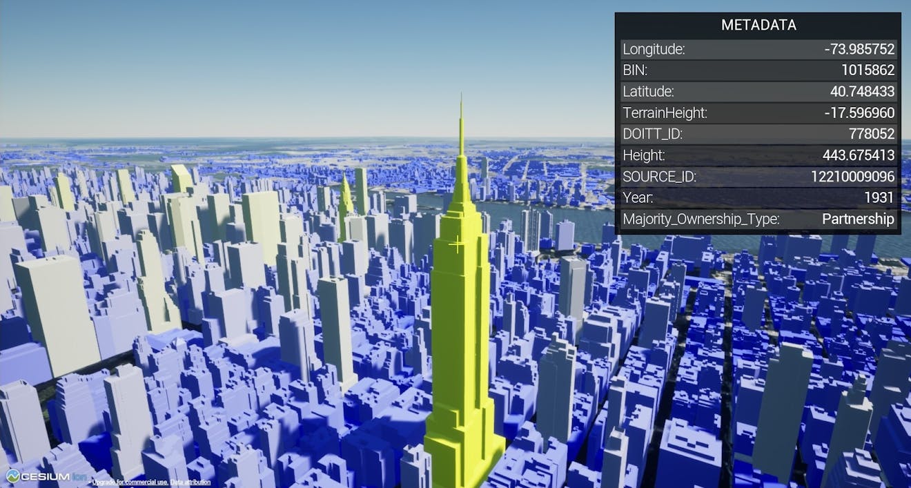
Metadata shown in a UMG widget from Cesium for Unreal Samples.
Want to see per-feature metadata in action without implementing it yourself? Check out the Cesium for Unreal Samples. Explore the premade sample scene and UMG widget. Feel free to experiment with it or include it in your own projects.
- Unreal Engine (4.26 or later)
- The Cesium for Unreal plugin (1.13.0+)
- Know how to set up a basic Cesium for Unreal application. Check out our Cesium for Unreal Quickstart guide for instructions on getting started with the Cesium for Unreal plugin.
- A Cesium ion account. If you don’t have one, you can log in with your Epic Games account.
This tutorial uses a tileset of 3D buildings in New York City. Each building (feature) in this tileset contains metadata properties, including height, age, and ownership.
1Start with a scene that includes Cesium World Terrain, CesiumSunSky, and a DynamicPawn. You can create a scene like this by following the Quickstart guide.
2Make sure you’re connected to Cesium ion in the Cesium panel.
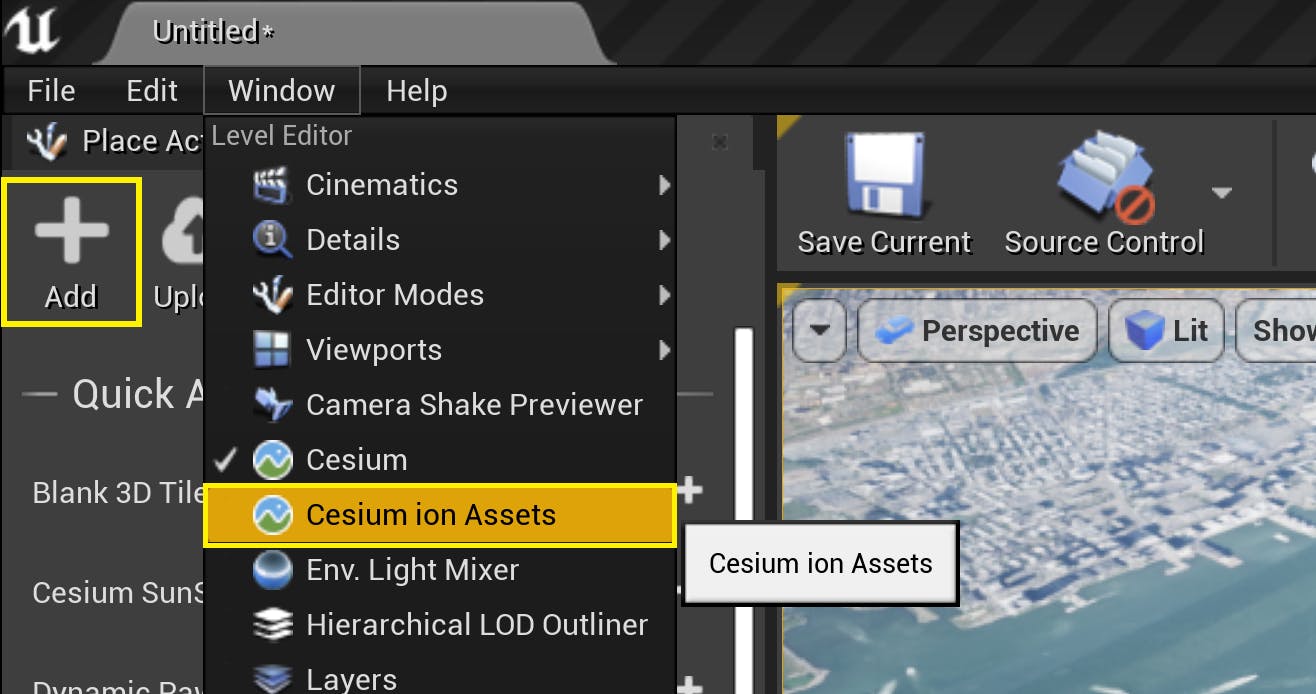
3Open the Cesium ion Assets window. If you don’t see the window in the Unreal Engine Editor, open it using Window/Cesium ion Assets, or press the Add button in the Cesium panel.
4Find New York City 3D Buildings in the asset list and select it. Click Add to Level.
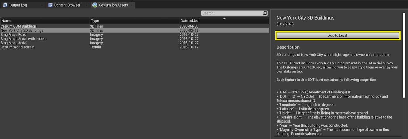
Is New York City 3D Buildings missing from the asset list? Visit the New York City 3D Buildings Asset Depot page and click Add to my assets. Then return to Unreal Engine. Click the blue Refresh button in the top left corner of the Cesium ion Assets panel to refresh the asset list.
5Double-click on the CesiumGeoreference in the World Outliner. In the Details panel, set the Georeference Origin to the following coordinates:
Origin Latitude: 40.700001
Origin Longitude: -74.002998
Origin Height: 418.0
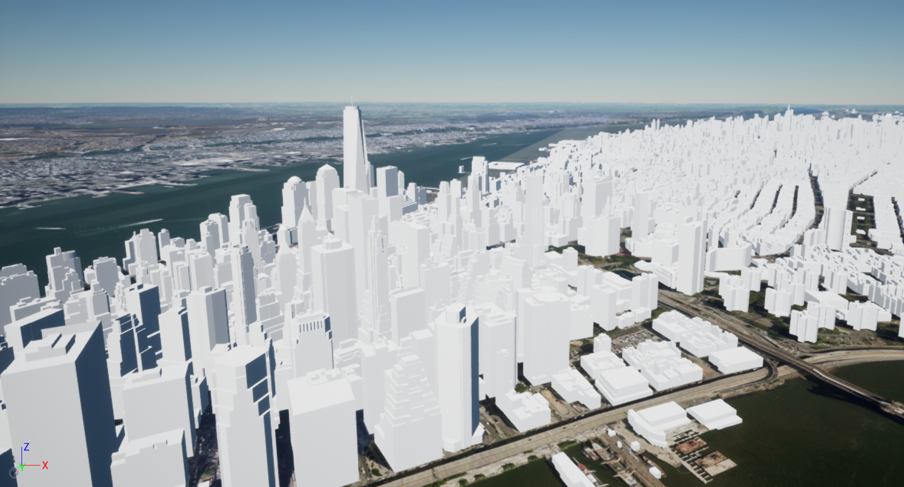
At this new location, you’ll see the tileset you just added.
6Right-click on the DynamicPawn in the World Outliner. Select Snap Object to View from the menu that appears to make sure the game will start at the new location.
In this section, you'll create a new material to style the buildings in NYC by their height and year of construction.
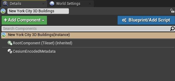
1Select the tileset you want to style from metadata and add a CesiumEncodedMetadataComponent to it.
2In the details panel of the new CesiumEncodedMetadataComponent, click the Auto Fill button. This will search the currently visible tiles for available metadata. Properties that are compatible with the material graph will be added to the component.
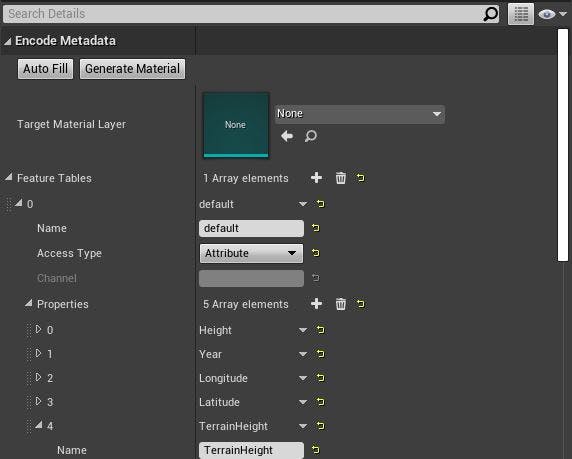
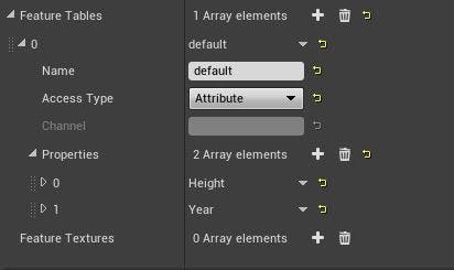
3Delete the Longitude, Latitude, and TerrainHeight properties by clicking on the arrow to the right of each property and selecting "Delete".
Be sure to delete properties from the Cesium Encoded Metadata component that aren't being used for the styling logic. Leaving unused properties will impact performance and cause excessive GPU texture memory usage. Deleted properties can be re-added if needed by using the Auto Fill button.
4Click the Generate Material button to create a material layer corresponding to the selected metadata properties.
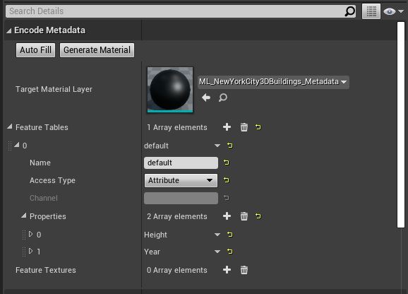
The generated material layer should automatically open. If not, open it by double-clicking it from the Target Material Layer parameter. You'll see several nodes generated by the Encoded Metadata component. The properties you set on the component will be available as out pins from the Resolve properties from <Feature Table Name> node.
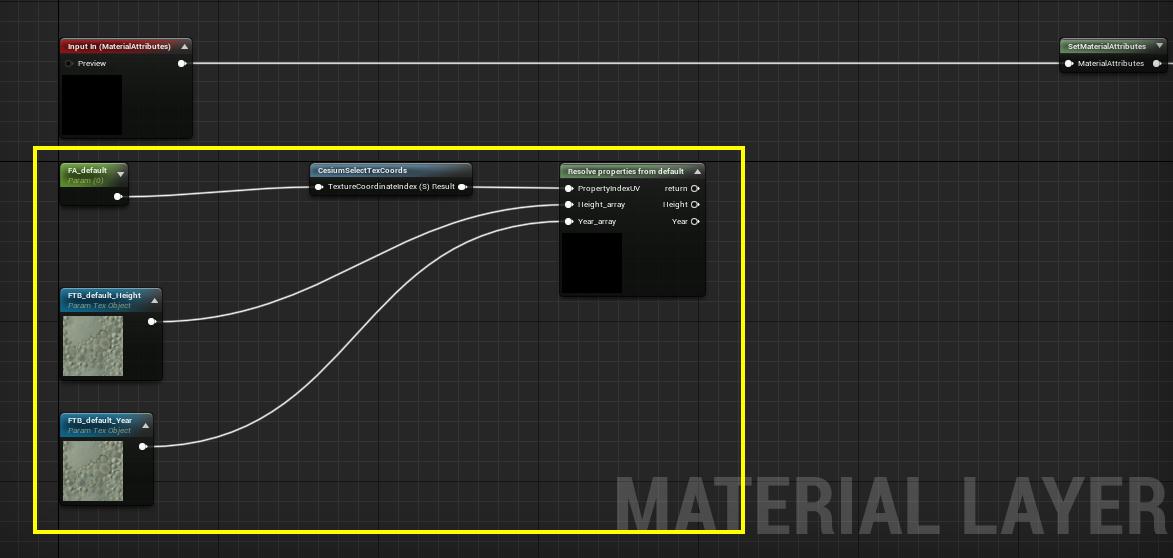
Be careful not to edit the auto-generated nodes. This will probably cause the encoded metadata to stop working.
5Connect the resolved property outputs to your custom logic for metadata styling.
Connect the resolved property outputs to your custom logic for per-feature styling.
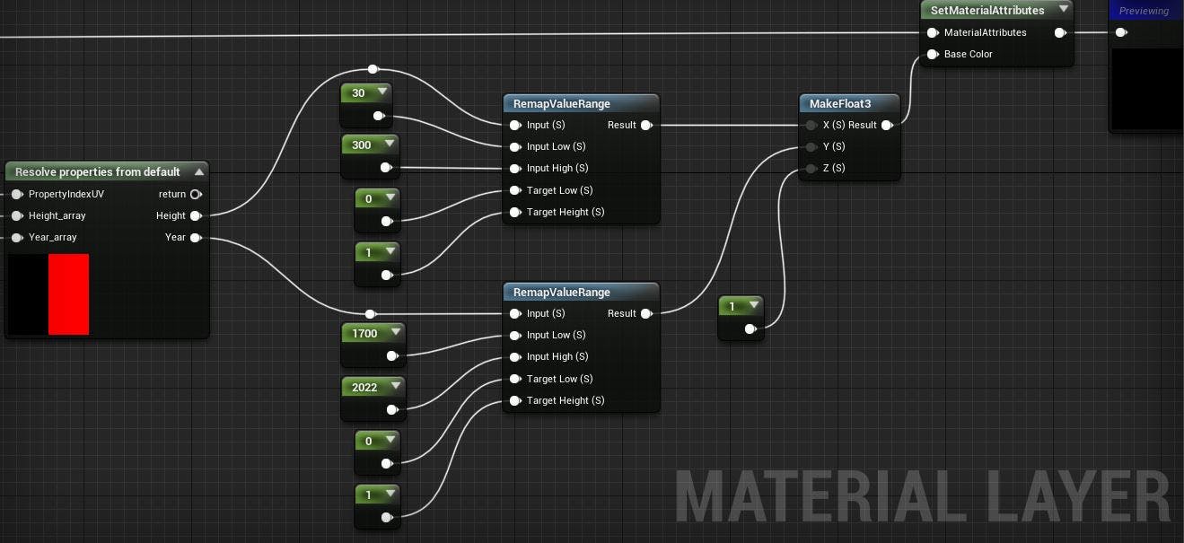
For example, here we color the NYC Buildings tileset with respect to its year of construction and height in meters.
The height of the building is used in the Red color channel, and the construction year is used in the Green color channel. The Blue color channel is set to a constant value of 1. Each property is clamped between a low and a high value to only show a certain range.
Try setting your own values in the low and high input pins of the Remap nodes to see how this changes the material.
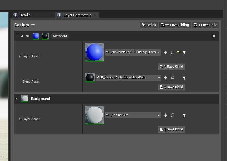
6Now we need to add the metadata material layer to a tileset material. Create a custom tileset material if you have not already. Add a material layer and name it Metadata.
7Add your material layer under Layer Asset. Then, select a Blend Asset that is appropriate for your styling logic. MLB_CesiumAlphaBlendBaseColor, which is included in the Cesium for Unreal plugin, can be used with the material graph above.
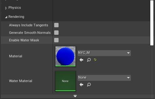
8In the tileset’s Details Panel, under the Rendering category, set the Material property to your custom material.
9Refresh the tileset if needed and you should be able to see the result of your per-feature styling logic!
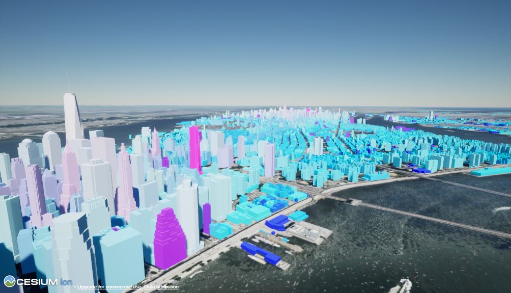
Your material will look like the above image if you copied the example node graph from Step 2.5 exactly. If you adjusted the material, your color scheme may look different.
This material allows you to see per-feature metadata about each building without querying each one individually. In this example, shorter buildings look more blue, and taller buildings look more red. How saturated each color appears depends on the construction year, so tall buildings that were constructed recently will look almost white. Likewise, deeper colors indicate an earlier construction year.
This can be used to spot missing metadata in the tileset. Very few buildings in Manhattan were built prior to 1700 (the low range input in this material), so bright pink or deep blue buildings more likely have no value or a value of 0 for their Year property.
Try experimenting with the material on your own. Some ideas to get you started:
- What happens if you change the limits, or swap around the color channels?
- How would you style the buildings by their latitude and longitude?
- Try making a material that only highlights buildings constructed after 2000.
10Modifications to the material can be done iteratively and nondestructively.
Change the styling logic by modifying the material layer directly.
To add or remove metadata properties, return to the CesiumEncodedMetadataComponent and repeat step 2 and step 3 (Auto Fill and delete unneeded metadata properties). To apply these changes, make sure the Target Material Layer is set to your material layer, then press the Generate Material button again.
Regenerating a material layer will not remove nodes that you have added to the material graph. However, if you remove properties that are actively being used in the material, any nodes that are connected to those properties will be disconnected.
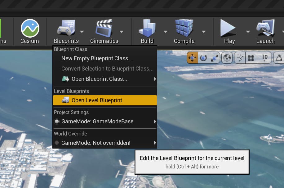
1Open the Level Blueprint Event Graph.
2Right-click in an empty space on the graph and search for “Left Mouse Button.” Create a Left Mouse Button input node.
3Click and drag the DynamicPawn actor from the World Outliner to the Level Blueprint graph. This will create a reference to your DynamicPawn in the Level Blueprint.
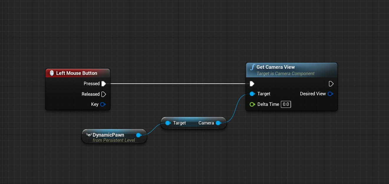
4Click on the blue pin of DynamicPawn and drag out to an empty spot on the graph. Release the mouse. Search for “Get Camera View” in the menu that appears. Select this node.
5Connect the Left Mouse Button input node to the Get Camera View node. Now, you should have a node graph that obtains the camera view from the Dynamic Pawn when the left mouse button is pressed.
6Drag out from the white pin of Get Camera View to create a LineTraceByChannel node.
7You’ll need to add a start and end for the line trace. Drag out from the blue DesiredView pin of Get Camera View and create a Break MinimalViewInfo node. Connect the yellow Location pin of Break MinimalViewInfo directly to the Start pin of LineTraceByChannel.
8To get the End location, create a GetRotationXVector node from the Rotation pin of BreakMinimalViewInfo.
Create a vector * float node and multiply the RotationXVector return value by 500000. This will ensure that the line trace is 500000 units long.
Create a vector + vector node to add the result to the camera location.
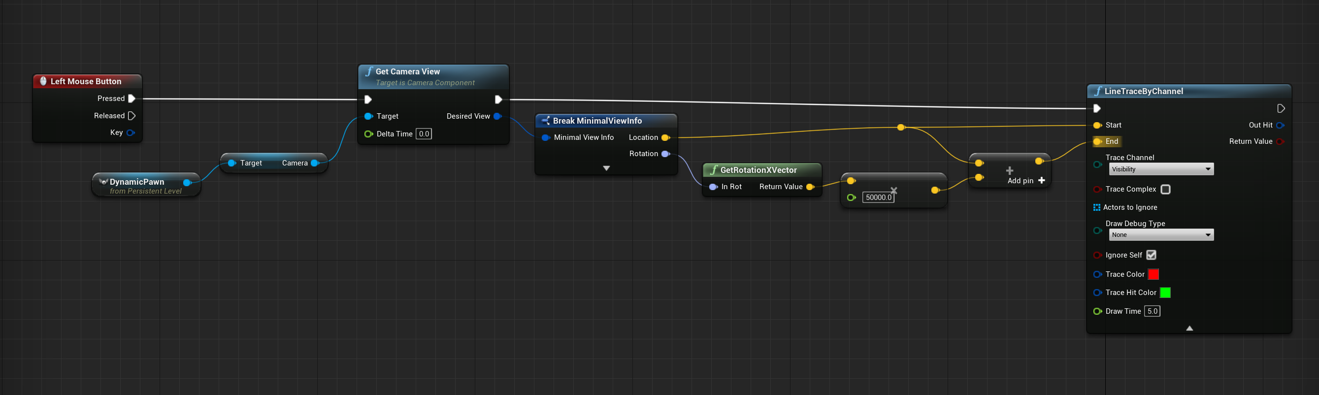
Depending on your application, you may want to set the multiplier of the RotationXVector higher or lower.
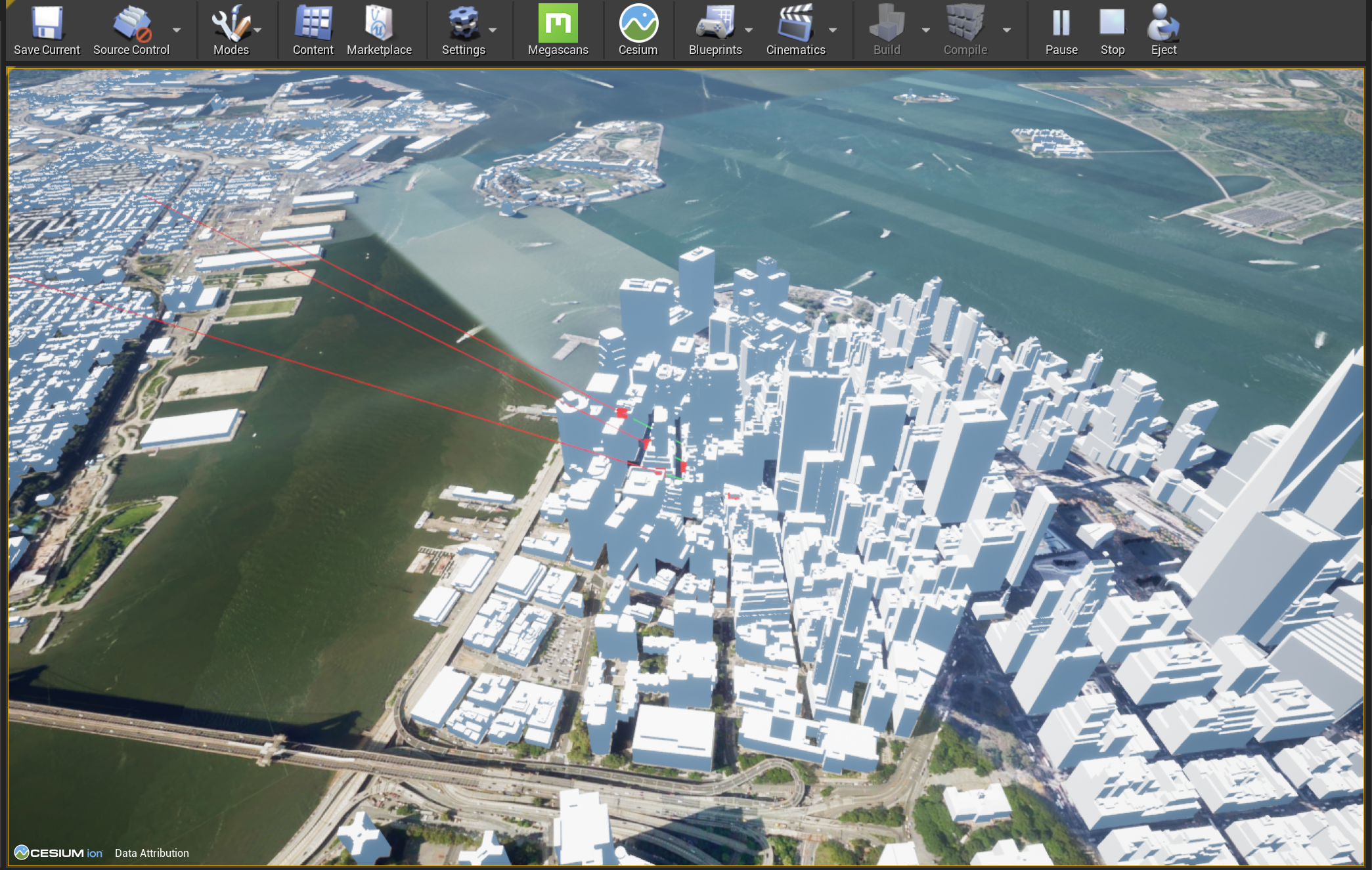
9Return to the LineTraceByChannel node. Change the Draw Debug Type to For Duration. Now, you’ll be able to see your line traces in the world. If you wish, you can also change Trace Color and Trace Hit Color. If you don’t see these options on the LineTraceByChannel node, click the small arrow near the center bottom of the node to expand the pins.
10Save and compile the Blueprint.
Now, you should have a blueprint that creates a line trace from the center of your screen and can collide with the world.
Test it out by playing in the editor. Left click to cast a ray from the center of your screen.
Right now, nothing happens if the line trace hits something. In the next step you’ll add logic to print information about the feature that the line trace hits.
In order to retrieve the relevant metadata for a building, the Blueprint will need to know which tileset feature the line trace is pointing at. In the steps below, you’ll learn how to use the Face Index and Hit Component of your line trace to identify the selected feature and look up the associated metadata.
1From the Out Hit pin of LineTraceByChannel, create a Break Hit Result node. Click on the arrow at the bottom of the node to expand the node and show all of the output pins. You’ll only need two of them: Hit Component and Face Index.
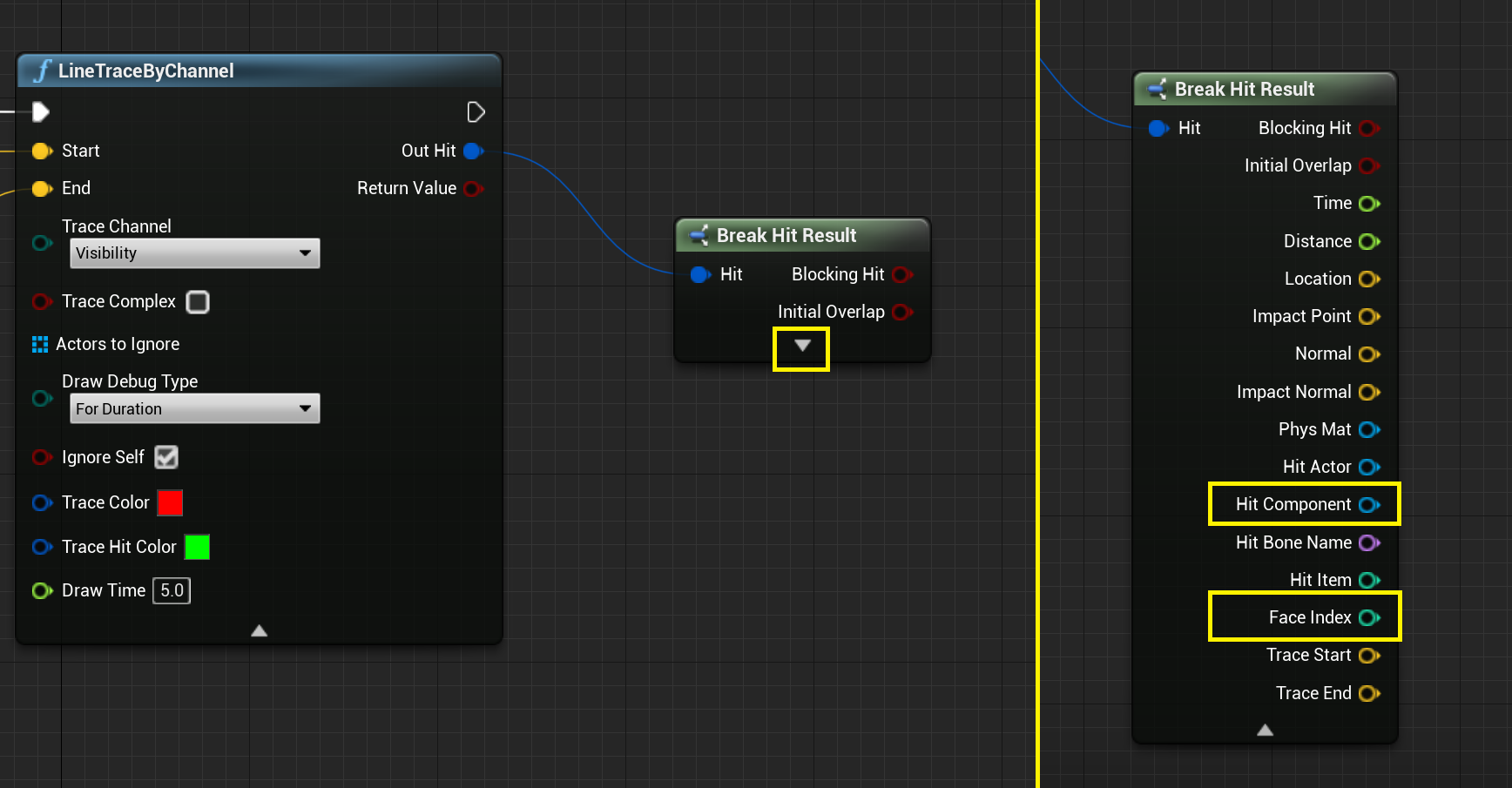
Hit Component represents the geometry component that the line trace has found. Face Index is the ID of the specific geometric face of the Hit Component. For example, the Hit Component represents the building model, and the Face Index represents the specific polygon face (perhaps a window or wall) that the line trace hit on the building.
2Create a Get Metadata Values as String for Face node. Connect Hit Component to Component and connect Face Index to Face ID.
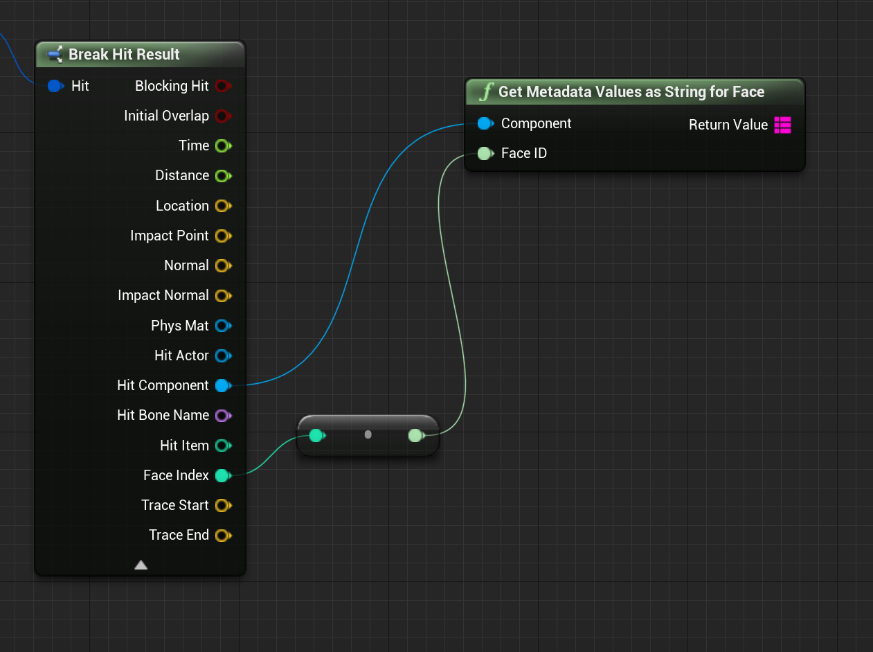
This node returns metadata properties for a given face, in string format. This data is expressed in Unreal Engine as a Blueprint Map. The map consists of the property name, or key, and the property value. Get Metadata Values as String for Face converts the values from their original type to a string, which is convenient for the purposes of printing these values on the screen. However, the conversion means that the original data type is lost.
If you require the original data types, use the node Get Metadata Values for Face. Visit the Per-Feature Metadata Technical Reference page for more information.
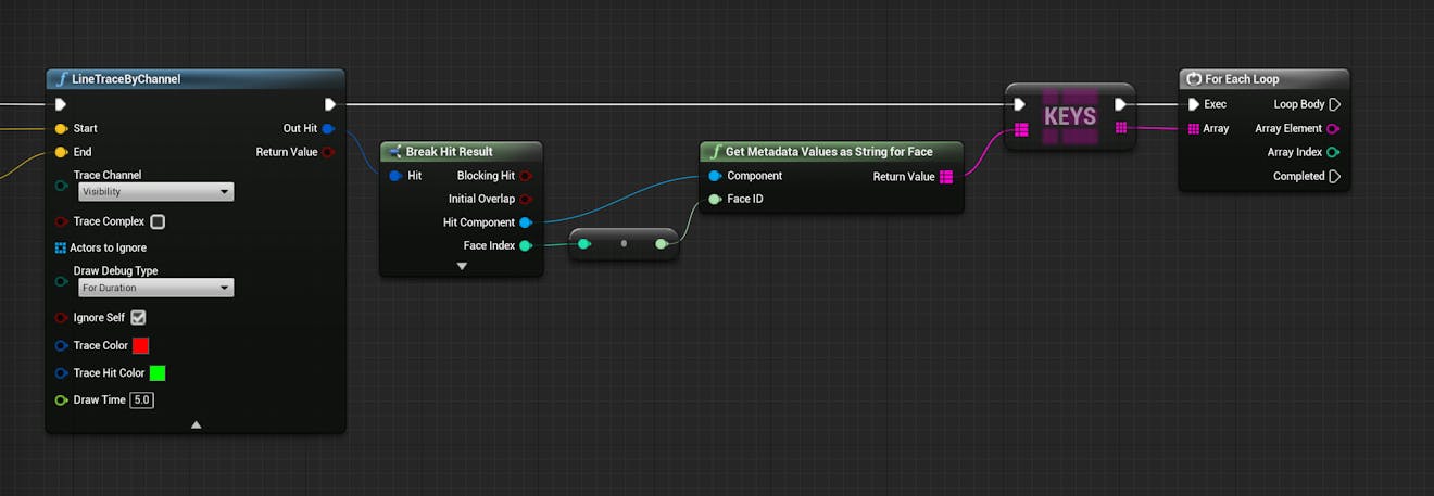
3From the output map, create a Keys node, which returns an array of every key in the table. Create a For Each Loop node to cycle through that array. Make sure to connect the Exec pins of these new nodes.
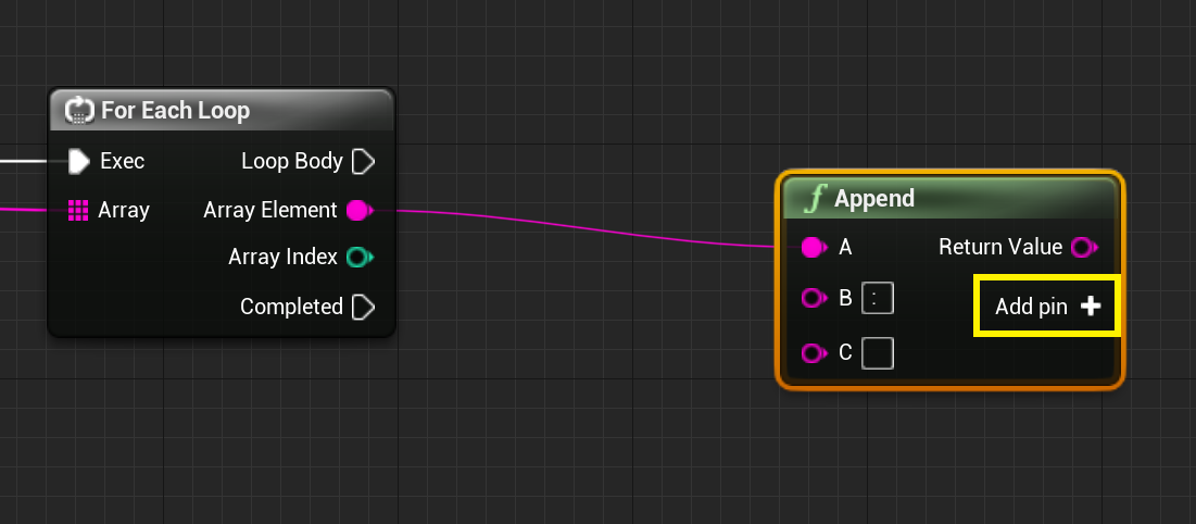
4Create an Append node to append strings. In order to view the metadata in an easily readable format, you’ll append a key to its value with a colon and space between the two.
Drag the Array Element from For Each Loop to the A pin of the Append node.
In the B pin, type a colon and a space (“: “).
Click Add pin on the Append node to add a third input.
5From the output of Get Metadata Values as String for Face, create a Find node. Connect the Array Element from For Each Loop to the empty pin on the Find node. Finally, connect the output of Find to the C pin of Append.
6Now, all you have to do is print the result. Create a Print String node in the Loop Body of For Each Loop. Connect the Return Value of Append to the In String pin of Print String.
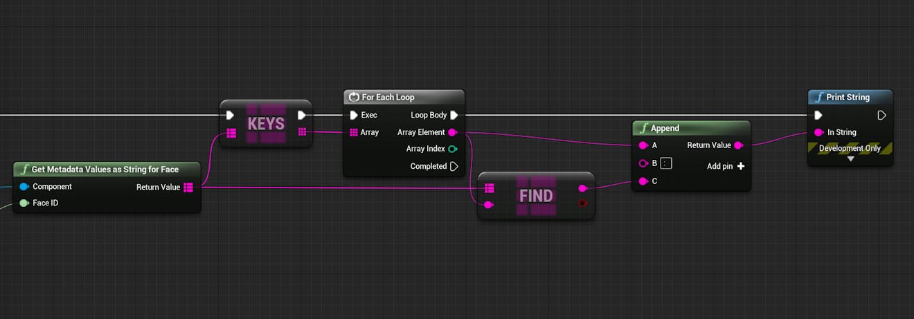
Your blueprint should resemble the following.
This is an interactive node graph. Right-click and drag to pan around the graph. To zoom in or out, press control/command and scroll with your mouse. You can also copy-and-paste nodes from this graph directly into your own blueprint.
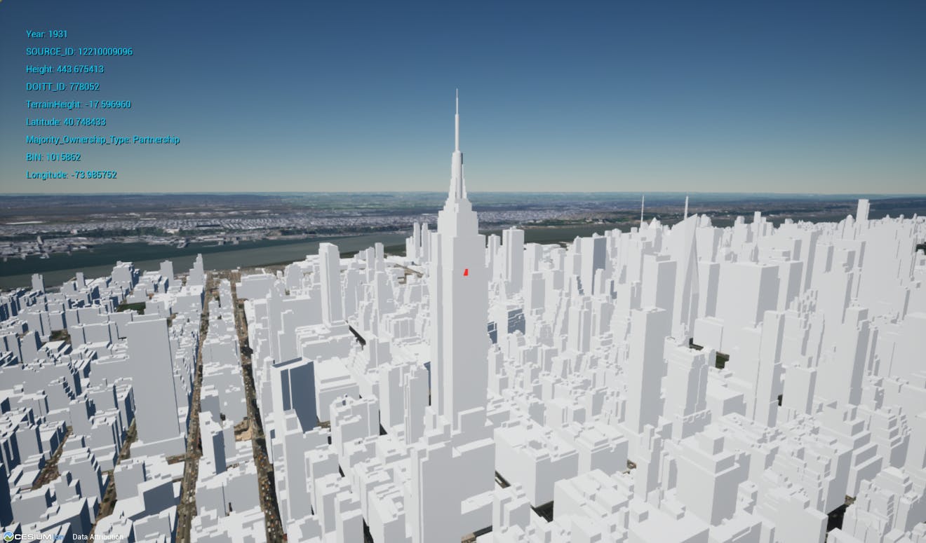
7Be sure to compile and save your Blueprint. Then, return to the editor and test it out! When you use the mouse to select a building, you should see the metadata properties associated with that feature in the top left corner.
You can edit the Print String node to change the color of the text or adjust the duration that it stays on screen.
Now that you've learned to access per-feature metadata properties, you can use them however you wish in your application. Level 6 of the Cesium for Unreal Samples contains an example UMG widget that displays these properties on the screen. You can use and modify that widget for your projects by downloading the Cesium for Unreal Samples.
If you're interested in doing more with per-feature metadata, check out the Per-Feature Metadata Technical Reference.
How are you using per-feature metadata in your Cesium for Unreal projects? Tweet your creations to us @CesiumJS.