Vector Tiles Blueprint Styling in Cesium for Unreal
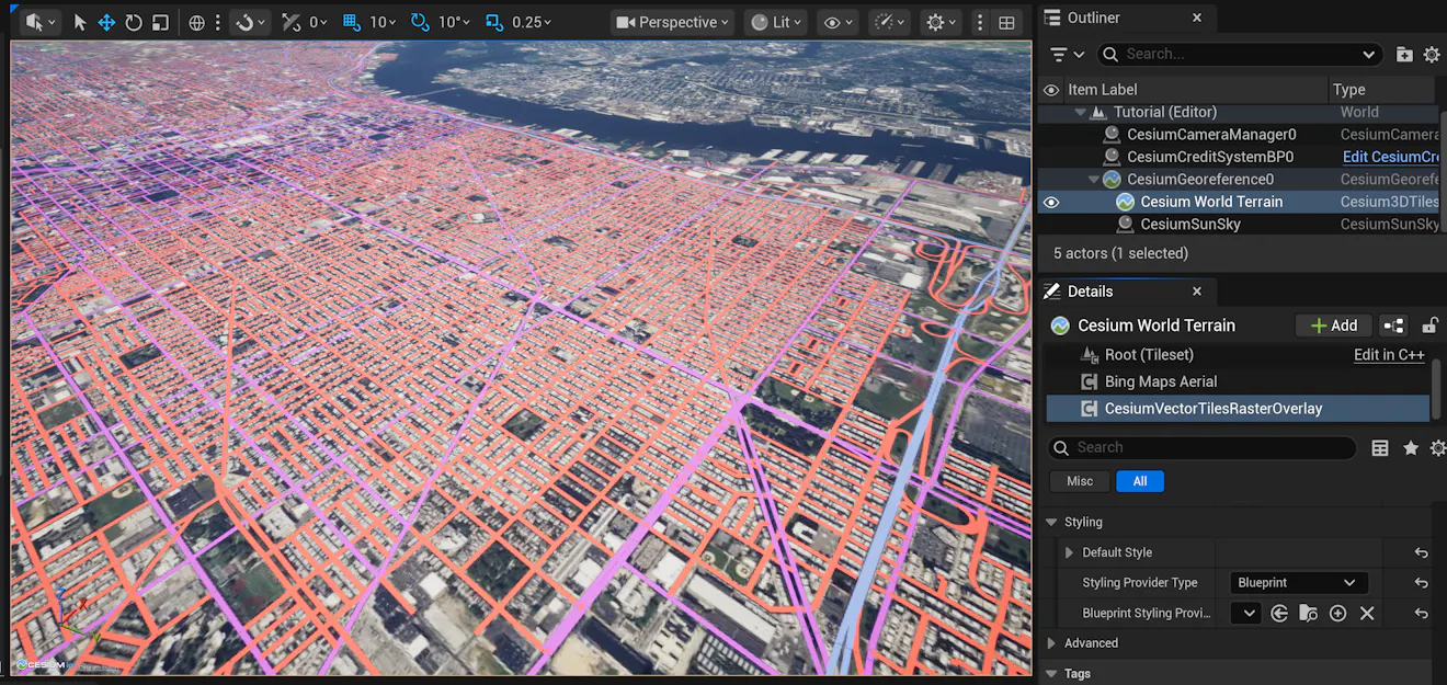
Building on the previous tutorial where you tiled vector data through Cesium ion and overlaid it onto a tileset using Cesium for Unreal, this tutorial guides you through applying custom styling to a vector tileset based on the metadata properties in the tile.
Prerequisites
- Unreal Engine 5.6+ and Cesium for Unreal v.2.30.0+
- Complete the previous tutorial to learn how to upload vector data to Cesium ion and create a Vector Tiles Raster Overlay displaying that tileset. You will use this tileset in this tutorial.
Starting with the VectorTilesRasterOverlay created in the previous tutorial, scroll down to the Styling section. Set the Styling Provider Type to Blueprint and click the Create New Blueprint button next to the Blueprint Styling Provider property.
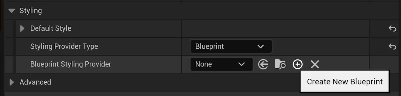
This will prompt you to choose a folder and a name for the new blueprint. We will call our blueprint StylingExample and save it in the Content folder.
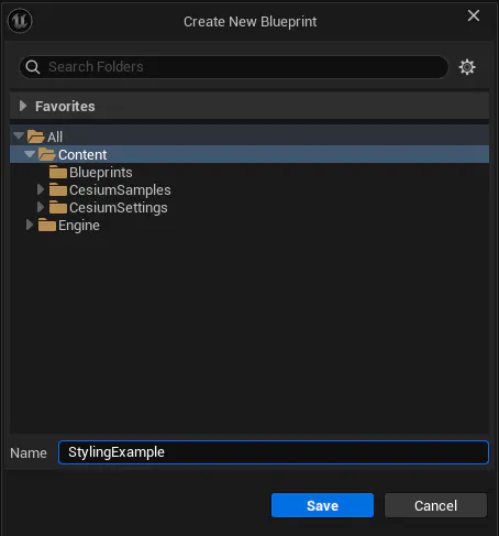
Click Save. This will create a new blueprint. Open this blueprint from the Content Drawer.
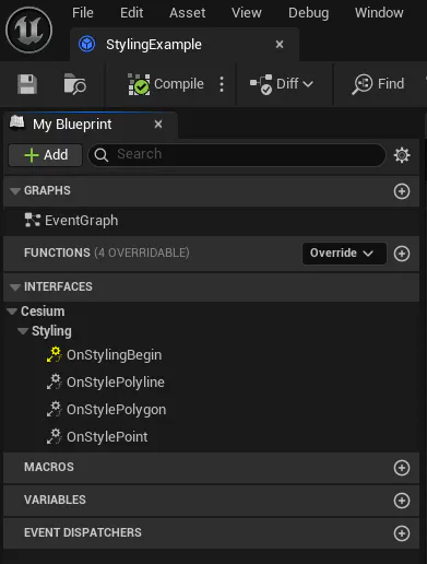
If you created this blueprint through the Create New Blueprint button as described above, you should see the functions OnStylingBegin, OnStylePolyline, OnStylePolygon, and OnStylePoint listed under the Interfaces section.
If you do not see these functions listed, press Class Settings on the menu bar at the top of the window.

At the bottom of the Details panel, there should be a section heading called Interfaces, and under it a list of Implemented Interfaces. If you don’t see the CesiumVectorTilesStylingCallbacks interface listed, use the Add dropdown to select it.
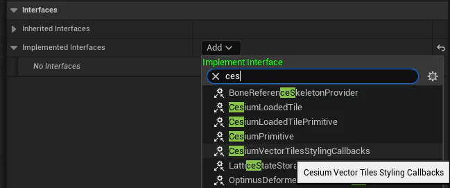
You now have a blueprint ready to be used to style vector tiles. There are four functions you can implement on the styling interface:
- OnStylingBegin will be called once for each tile styled, before any of the other functions are called. You can use it to look up and cache information that the other functions will need for styling – especially tile metadata.
- OnStylePolyline will be called once for every polyline that needs to be styled. It receives the feature ID (which can be used to look up metadata) as well as the positions making up the polyline in an array of Longitude, Latitude, Height FVectors.
- OnStylePolygon is similar to the above but will be called instead for each polygon that needs to be styled.
- OnStylePoint is similar to the above but will be called instead for each point that needs to be styled.
To demonstrate how to use your new styling blueprint to style a tileset, we will start with OnStylingBegin. Here, we will obtain the tile’s metadata that we will use in later steps for styling.
Open the OnStylingBegin function under the Interfaces section of My Blueprint. The function receives one parameter – the metadata of the model (the tile) that will be styled.
This Cesium Model Metadata contains one or more Property Tables. Each Property Table represents a “set” of metadata. A tile could use multiple Property Tables to represent metadata collected across multiple dates, or from different sources; however, the Philadelphia Streets dataset we created last tutorial has only one Property Table, as is most common.
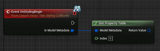
First, we will obtain the first (and only) Property Table available. The next question is what properties are available? We will answer this question by printing out each one in the Output Log. We can do this with a few Blueprint nodes.
Copy the code for this Blueprint.
Here, we are taking the Property Table and calling Get Properties on it, which returns a Map. We iterate through this map, printing the key, value type, and value component type to the log. We also add a separator when the loop completes to make the output easier to read.
If you compile and save this blueprint and click Refresh Tileset on the Tileset that the Vector Tiles Raster Overlay is attached to, you should see line after line like the following in the Output Log.
LogBlueprintUserMessages: ---
LogBlueprintUserMessages: stcl2_id: String None
LogBlueprintUserMessages: length: Scalar Float 64
LogBlueprintUserMessages: responsibl: String None
LogBlueprintUserMessages: l_t_add: Scalar Int 64
LogBlueprintUserMessages: multi_rep: Scalar Int 64
LogBlueprintUserMessages: st_type: String None
LogBlueprintUserMessages: Shape__Length: Scalar Float 64
LogBlueprintUserMessages: zip_right: Scalar Int 64
LogBlueprintUserMessages: suf_dir: String None
LogBlueprintUserMessages: stname: String None
LogBlueprintUserMessages: oneway: String None
LogBlueprintUserMessages: seg_id: Scalar Int 64
LogBlueprintUserMessages: st_code: Scalar Int 64
LogBlueprintUserMessages: l_f_add: Scalar Int 64
LogBlueprintUserMessages: lpoly_: String None
LogBlueprintUserMessages: fnode_: Scalar Int 64
LogBlueprintUserMessages: pre_dir: String None
LogBlueprintUserMessages: tnode_: Scalar Int 64
LogBlueprintUserMessages: newsegdate: String None
LogBlueprintUserMessages: streetlabe: String None
LogBlueprintUserMessages: objectid: Scalar Int 64
LogBlueprintUserMessages: zip_left: Scalar Int 64
LogBlueprintUserMessages: update_: String None
LogBlueprintUserMessages: class: Scalar Int 64
LogBlueprintUserMessages: stcl2_: String None
LogBlueprintUserMessages: r_t_add: Scalar Int 64
LogBlueprintUserMessages: r_hundred: Scalar Int 64
LogBlueprintUserMessages: st_name: String None
LogBlueprintUserMessages: r_f_add: Scalar Int 64
LogBlueprintUserMessages: rpoly_: String None
LogBlueprintUserMessages: l_hundred: Scalar Int 64
LogBlueprintUserMessages: ---
Because OnStylingBegin is called for every tile that needs to be styled, the log will be filled with messages. This is fine; we're only using this as a debugging step.
The next thing we need to do is to select one of the properties listed above to use for styling. Understanding what these properties represent can be tricky from just the names and types. Thankfully, the City of Philadelphia provides us with a Metadata Catalog for this dataset that describes each property in detail. When bringing your own data, you will likely already have a better idea of what properties it contains or have documentation similar to this catalog.
For styling this dataset, we will use the “class” property. According to the Metadata Catalog, this property contains the “street class” of the line: if the road is a highway, a local road, a driveway, etc.
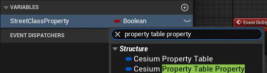
To use this property from the OnStylePolyline function, we will have to store the Property Table Property to look up later. We can do this very easily. First, create a new variable on the Blueprint and name it StreetClassProperty.

Click the type of the variable (which defaulted to Boolean) and use the dropdown and search functions to set the variable type to Cesium Property Table Property.
Finally, we need to set this variable in OnStylingBegin. We can do this by using the Find Property function on the Property Table with the Property Name of “class” and setting StreetClassProperty to its return value.
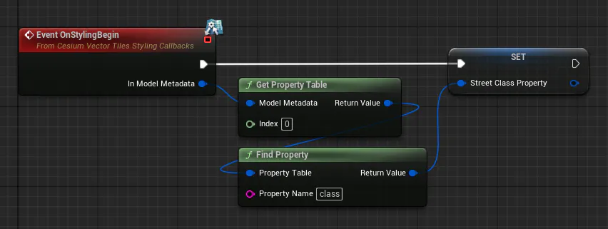
We are now ready to use this property for styling.
Open up the OnStylePolyline function under Interfaces. This function receives the feature ID of the polyline when it is called. We can use this feature ID to look up the value of our property.
Recall that in the log messages we printed out above, the “class” property had a type of Scalar and a component type of Int 64. This means that it has only one value for each polyline, and that we can access it using the function Get Integer 64 on the Property Table Property we saved in the previous step.
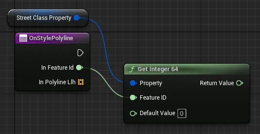
Next, we need to turn this integer into a style. Here, we will use its value to select a color for the line. The Metadata Catalog linked above will inform us of how to use the value of this property to style a line. Let’s implement the following styling rules:
- If the road is an Expressway (value = 1), color it blue
- If the road is an Arterial (value = 2 or value = 3), color it magenta
- Else, color it red
This chain of logic is fairly easy to accomplish using the Select Color node.
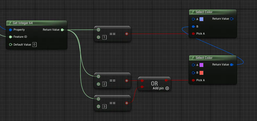
Finally, we have a color. Now, we need to turn it into a Cesium Vector Line Style to be returned. This can easily be done using the Make Cesium Vector Line Style node.
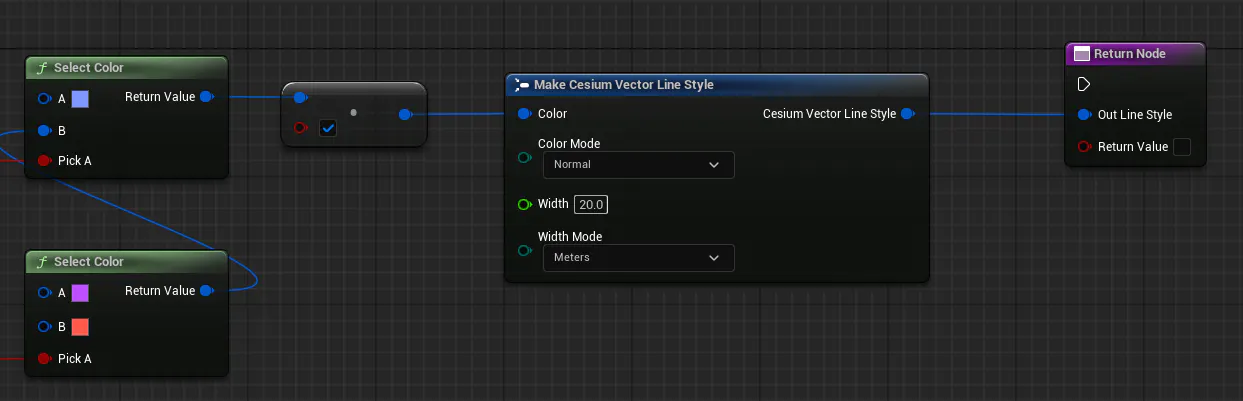
This struct has the same properties as found in the Default Style property of the Vector Tiles Raster Overlay. Here, we can provide our calculated color, as well as set the width of the line. We will set Width to 20.0 and Width Mode to Meters, just as we did in the Default Style we set last tutorial.
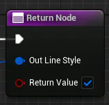
There’s just one thing we need to do before finishing our blueprint – we need to check that Return Value box! When true, this Boolean tells the overlay that we want to use our own custom style. If false, the default style will be used. This can be used to only apply styling to a subset of geometry in a tile.
Altogether, your blueprint should look like this:
Copy the code for this Blueprint.
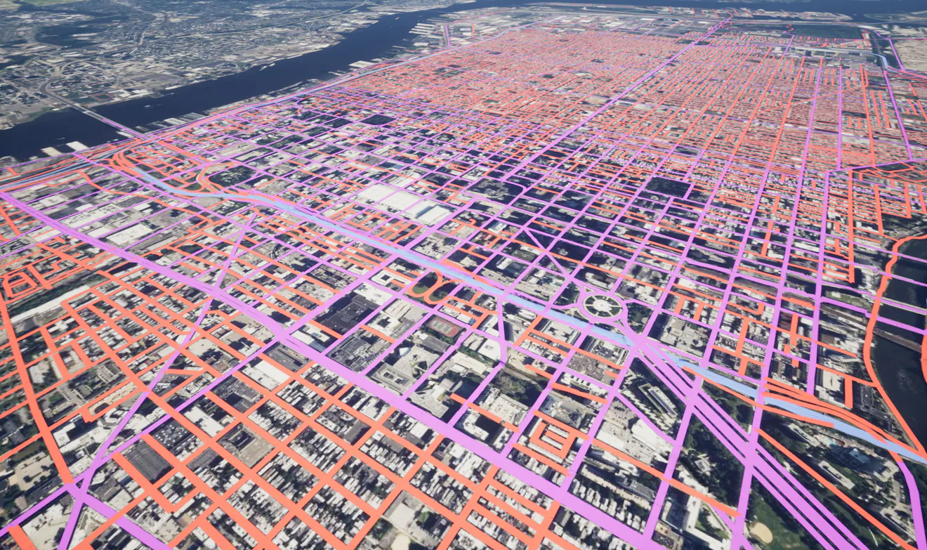
Finally, we can compile and save our blueprint and click Refresh Tileset on the tileset our overlay is attached to. You should now see the lines in the tileset styled by their street class: