Build a Flight Tracker with Cesium for Unreal
This tutorial will walk through the process of visualizing a flight from San Francisco to Copenhagen using real-world flight data.
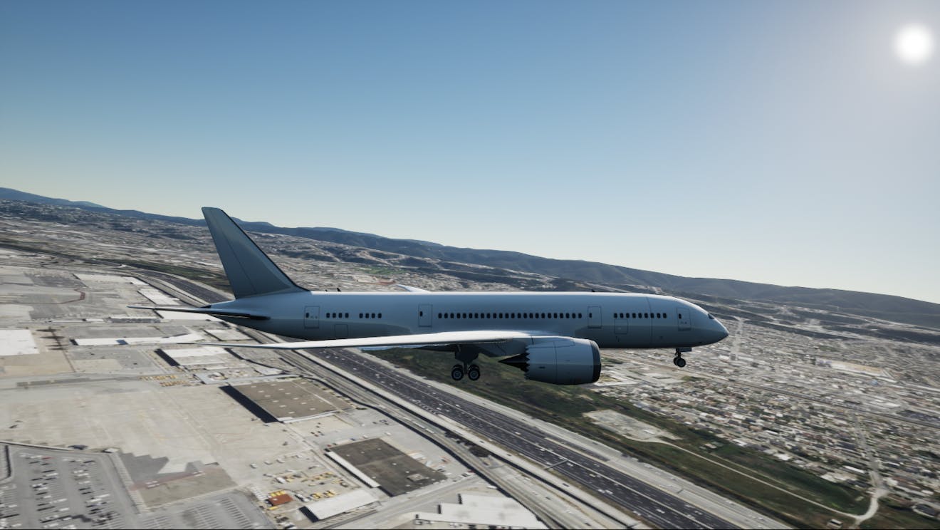
Flying over San Francisco, CA, USA.
You’ll learn how to:
- Import real-world flight data into Unreal Engine.
- Create a flight path using the data and USplineComponent.
- Import a model of an airplane and have the plane follow the flight path.
- Switch between different camera views in-flight.
- An installed version of Unreal Engine 5.0+. This tutorial uses Unreal Engine 5.4. For instructions on installing Unreal Engine, visit the Unreal Engine download page and refer to the Installing Unreal Engine guide for detailed instructions.
- Visual Studio 2022 with the Desktop Development with C++ workload.
- Cesium for Unreal version 2.0.0 or later.
- Know how to set up a basic Cesium for Unreal application. Check out our Cesium for Unreal Quickstart guide.
You can start with the 01_CesiumWorld level from the Cesium for Unreal Samples on the Unreal Engine Marketplace or create a new level. If starting a new level, make sure to populate the level with at least Cesium World Terrain and some lighting, either with CesiumSunSky or your own custom lighting. Check out the Quickstart guide to learn how to set up a new level with Cesium for Unreal.
For this tutorial, the CesiumGeoreference is set to the coordinates of San Francisco International Airport (SFO), where the flight originates.
Origin Latitude = 37.61779
Origin Longitude = -122.390533
Origin Height = 0.0

SFO visualized with Cesium World Terrain and Bing Maps Aerial imagery.
The PlaneTrack class will contain logic to process the flight data and generate position points for the spline which represents the flight path.
1Add a new C++ class by going to Tools > New C++ Class… at the top left corner of the Unreal Editor. Select Actor as the parent class.
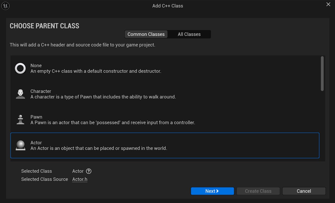
Click Next. On the following page, set the name of the new class to "PlaneTrack"; then click Create Class.
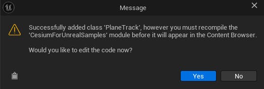
Once the class is added, you may get the following message. Click Yes to jump straight into the code.
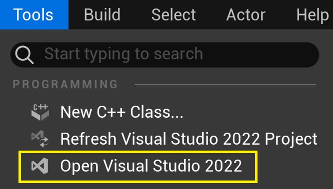
Visual Studio should automatically open the file. If not, open the project in Visual Studio by going to Tools > Open Visual Studio 2022.
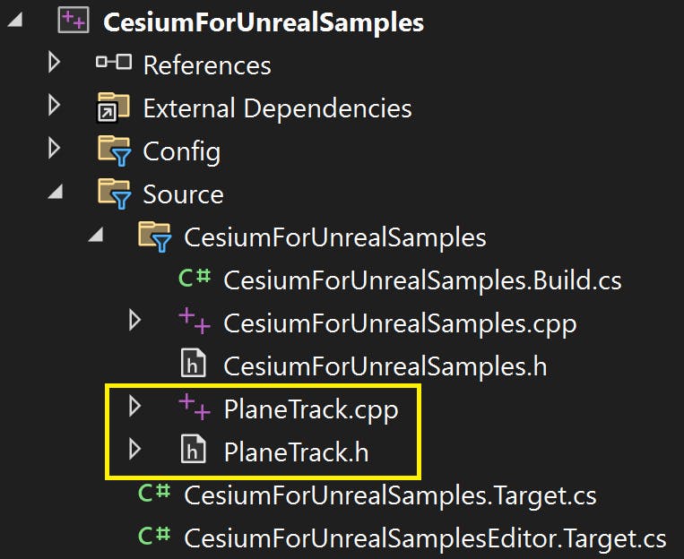
The new C++ files can be found in the Source folder of the Visual Studio project. (Your view may be different, depending on the structure of your project.)
2Add the following code snippet to the project's .Build.cs file, which can also be found in the Source folder:
// Add Cesium for Unreal plugin dependency path
PrivateDependencyModuleNames.AddRange(new string[] { "CesiumRuntime" });
3Let's add some member variables to the PlaneTrack class to store the flight data and spline and convert the data to the appropriate coordinate system. Import the necessary libraries and add the following public variables to PlaneTrack.h:
...
// Add import paths. Make sure they go above the PlaneTrack.generated.h line
#include "Components/SplineComponent.h"
#include "CesiumGeoreference.h"
#include "Engine/DataTable.h"
...

public:
  // Spline variable to represent the plane track
  UPROPERTY(BlueprintReadOnly, Category = "FlightTracker")
    USplineComponent* SplineTrack;

  // Cesium class that contains useful functions for coordinate conversion
  UPROPERTY(EditAnywhere, Category = "FlightTracker")
    ACesiumGeoreference* CesiumGeoreference;

  // An Unreal Engine data table to store the raw flight data
  UPROPERTY(EditAnywhere, Category = "FlightTracker")
    UDataTable* AircraftsRawDataTable;
4Navigate to PlaneTrack.cpp and initialize the SplineTrack variable in the PlaneTrack constructor as follows:
APlaneTrack::APlaneTrack()
{
  // Set this actor to call Tick() every frame.  You can turn this off to improve performance if you don't need it.
  PrimaryActorTick.bCanEverTick = true;

  // Initialize the track
  SplineTrack = CreateDefaultSubobject<USplineComponent>(TEXT("SplineTrack"));
  // This lets us visualize the spline in Play mode
  SplineTrack->SetDrawDebug(true);

  // Set the color of the spline
  SplineTrack->SetUnselectedSplineSegmentColor(FLinearColor(1.f, 0.f, 0.f));
}
We will set the ACesiumGeoreference and UDataTable variables inside the Unreal Editor.
5Before moving on to the next step, save and compile the code. You can take advantage of Live Coding to compile the code while in the Unreal Editor by pressing Ctrl + Alt + F11.
Next, you are going to use real flight data from San Francisco to Copenhagen. This data is collected by FlightRadar24.
Height in Cesium for Unreal is expressed in meters relative to the WGS84 ellipsoid. The data has been pre-processed to convert the heights from feet relative to mean sea level to meters relative to the ellipsoid. You can download the converted data here.
The flight data in Microsoft Excel.
For the PlaneTrack class to access the data to perform coordinate conversions, you will use the Unreal Engine DataTable to store the data inside the project. In this step, you will create a data structure to represent the structure of the flight data.
1In PlaneTrack.h, insert this snippet of code directly below the imports to define the flight database structure:
USTRUCT(BlueprintType)
struct FAircraftRawData : public FTableRowBase
{
  GENERATED_USTRUCT_BODY()

  public:
    FAircraftRawData()
      : Longitude(0.0)
      , Latitude(0.0)
      , Height(0.0)
    {}

  UPROPERTY(EditAnywhere, Category = "FlightTracker")
    double Longitude;
  UPROPERTY(EditAnywhere, Category = "FlightTracker")
    double Latitude;
  UPROPERTY(EditAnywhere, Category = "FlightTracker")
    double Height;
};
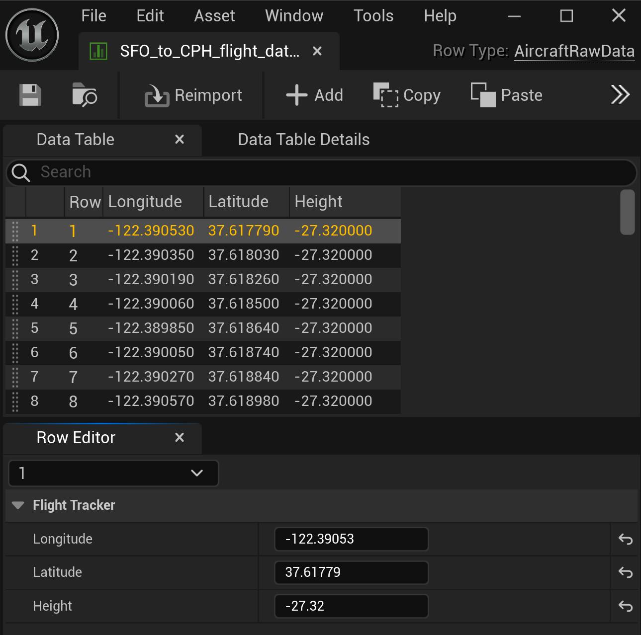
The structure contains three member variables: Longitude, Latitude, and Height. These variables correspond to the column names in the raw data table above. Also notice that the structure inherits from FTableRowBase.
Save and compile your code.
2Drag-and-drop the .csv data file into the Unreal Engine Content Browser. Select AircraftRawData from the dropdown under Choose DataTable Row Type:
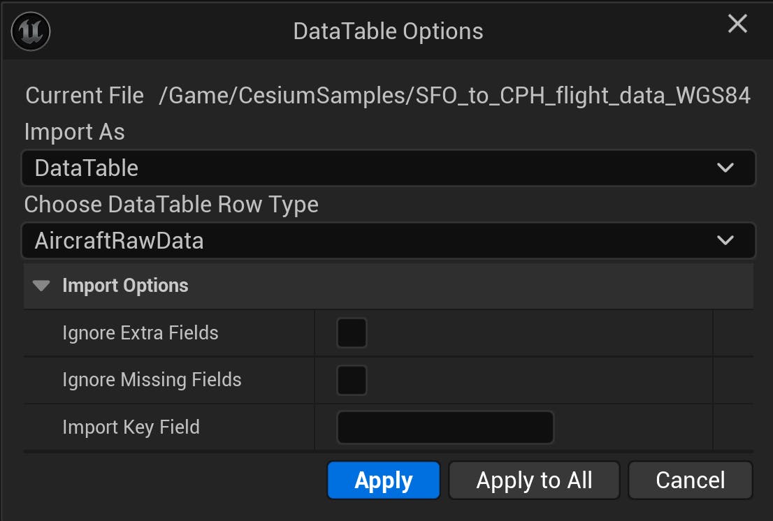
Click Apply and double-click on the new UDataTable object in the Content Browser to open the data table:
Troubleshooting: If you receive a an error saying that Unreal Engine is unable to import, check to see if the data is saved within the the project folder. This error can occur if the data file is saved elsewhere.
In this step, you will add some more code to the PlaneTrack class to complete the rest of the functionality needed to create the spline path.
1Add the following imports to PlaneTrack.h, above the PlaneTrack.Generated.h line.
// Imports should be placed above the PlaneTrack.Generated.h line.
...
#include <CesiumGeospatial/Cartographic.h>
#include <CesiumGeospatial/Ellipsoid.h>
These lines import functionality from Cesium Native to aid with geospatial math in our Unreal project.
While still in PlaneTrack.h, add the following function at the end of the APlaneTrack class definition.
public:
  // Function to parse the data table and create the spline track
  UFUNCTION(BlueprintCallable, Category = "FlightTracker")
    void LoadSplineTrackPoints();
2Switch to PlaneTrack.cpp. Add the following code snippet to create the body of LoadSplineTrackPoints. This is where the majority of the computation will be done.
void APlaneTrack::LoadSplineTrackPoints()
  {
    if (this->AircraftsRawDataTable != nullptr && this->CesiumGeoreference != nullptr)
    {
      int32 PointIndex = 0;
      for (auto& row : this->AircraftsRawDataTable->GetRowMap())
      {
        FAircraftRawData* Point = (FAircraftRawData*)row.Value;
        // Get row data point in lat/long/alt and transform it into UE points
        double PointLatitude = Point->Latitude;
        double PointLongitude = Point->Longitude;
        double PointHeight = Point->Height;

        // Compute the position in UE coordinates
        FVector SplinePointPosition  = this->CesiumGeoreference->TransformLongitudeLatitudeHeightToUnreal(FVector(PointLongitude, PointLatitude, PointHeight));
        this->SplineTrack->AddSplinePointAtIndex(SplinePointPosition, PointIndex, ESplineCoordinateSpace::World, false);

        // Get the up vector at the position to orient the aircraft
        const CesiumGeospatial::Ellipsoid& Ellipsoid = CesiumGeospatial::Ellipsoid::WGS84;
        glm::dvec3 upVector = Ellipsoid.geodeticSurfaceNormal(CesiumGeospatial::Cartographic(FMath::DegreesToRadians(PointLongitude),
FMath::DegreesToRadians(PointLatitude),
FMath::DegreesToRadians(PointHeight)));

        // Compute the up vector at each point to correctly orient the plane
		  FVector4 ecefUp(upVector.x, upVector.y, upVector.z, 0.0);
		  FMatrix ecefToUnreal = this->CesiumGeoreference->ComputeEarthCenteredEarthFixedToUnrealTransformation();			  FVector4 unrealUp = ecefToUnreal.TransformFVector4(ecefUp);
		  this->SplineTrack->SetUpVectorAtSplinePoint(PointIndex, FVector(unrealUp), ESplineCoordinateSpace::World, false);

        PointIndex++;
      }
      this->SplineTrack->UpdateSpline();
    }
  }
Save and compile the code.
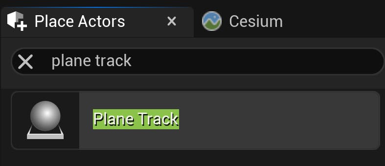
3Navigate back to the Unreal Editor to add the flight track to the scene. In the Place Actors panel, search for "Plane Track". Then drag and drop it into the viewport.
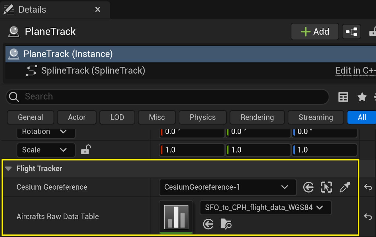
4Select the PlaneTrack actor. In the Details panel, look for the Flight Tracker category. Set the Cesium Georeference variable to the CesiumGeoreference instance in your scene. Then set the Aircrafts Raw Data Table variable to the data table added in Step 3.
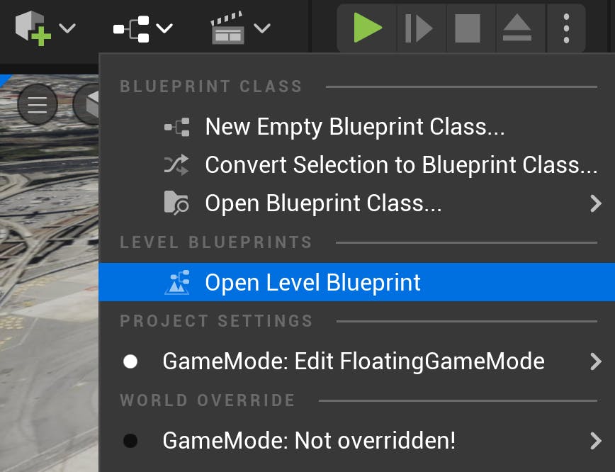
5Navigate to the Level Blueprint. Here you're going to add some Blueprint nodes to populate the spline path.
6Look for the Event BeginPlay node. This node is called at the very beginning in Play mode. Drag and drop the PlaneTrack actor from the World Outliner into the Blueprint. Then drag a connection from this node and search for and add the Clear Spline Points function node. Clear Spline Points is added because the spline has two default points when added to the level. These two points are arbitrary and not needed in this tutorial.
7From the PlaneTrack object node, drag another connection and search for Load Spline Track Points. Connect the Clear Spline Points and the Load Spline Track Points nodes, and connect the Event BeginPlay node to the Clear Spline Points node. The final Blueprint network looks like this:
8Because spline visualization is off by default, turn it on by selecting the viewport, pressing the` key (usually under the Esc key) on your keyboard, and entering ShowFlag.Splines 1.
Click Compile at the top left corner of the Blueprint Editor. To confirm everything is set up correctly, click Play in the main editor. You should be able to see the data points connected by a spline curve that starts at a terminal building in SFO like this:
The final step to complete the flight tracker is adding an aircraft that follows the spline path. For the aircraft mesh, you can use any model. This tutorial uses a Boeing 787 aircraft model from TurboSquid that you can download for free.
1In the Content Browser, import the aircraft model into the content browser by selecting Add > Import to Game/[Path]/. You can inspect the model in the Static Mesh Editor:
![CFUE flight tracker tutorial: In the Content Browser, import the aircraft model into the content browser by selecting Add > Import to Game/[Path]/. You can inspect the model in the Static Mesh Editor.](https://images.prismic.io/cesium/aHgS9kMqNJQqH_FD_11_AirplaneMesh.png?auto=compress%2Cformat&w=1320)
2Right-click in a blank area of the Content Browser and select Blueprint Class. When prompted to pick the Parent Class, select Actor. Name the class “BP_Aircraft” (BP stands for Blueprint). This class will contain the logic to move the aircraft along the spline path.
3Double-click on the new Blueprint class to access the Blueprint Editor. Under the Components list in the top left, click Add Component and search for “Static Mesh”.
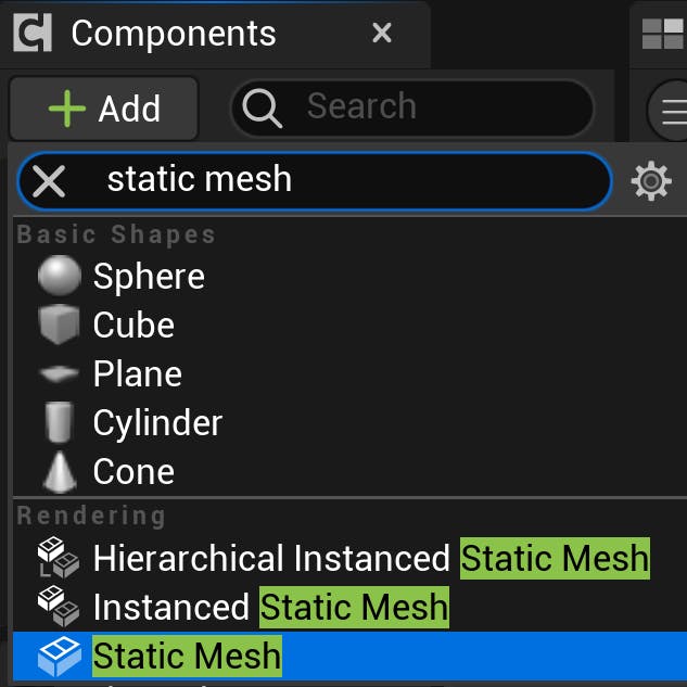
Add it to the component list and name it “AircraftMesh”.
4With this new component selected, locate the Details panel to the right side of the Blueprint Editor. Find the Static Mesh variable. In the dropdown menu, find and select the aircraft mesh you imported earlier.
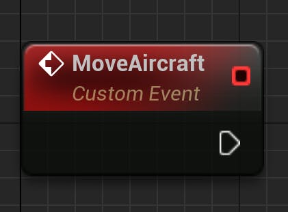
5Head to the Event Graph by clicking the Event Graph tab at the top of the Blueprint Editor. Right-click anywhere in the Event Graph and search for “Custom Event”. Click to create the event node; then name it “MoveAircraft”.
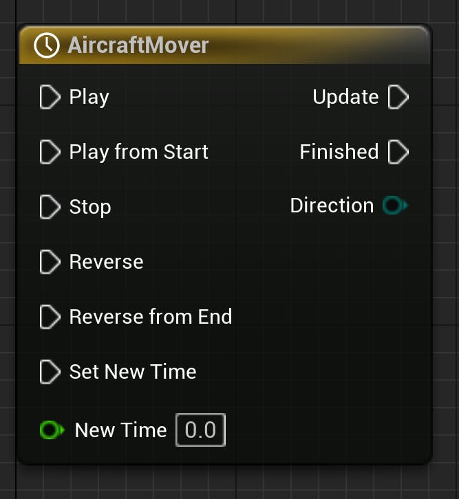
6Right-click again in the Event Graph and search for “Add Timeline”. Click to create the Timeline node, and then give it a name.
7Double-click on the Timeline node to open the Timeline Editor. Create a float curve by clicking the Track button at the top left corner of the editor then selecting Add Float Track.
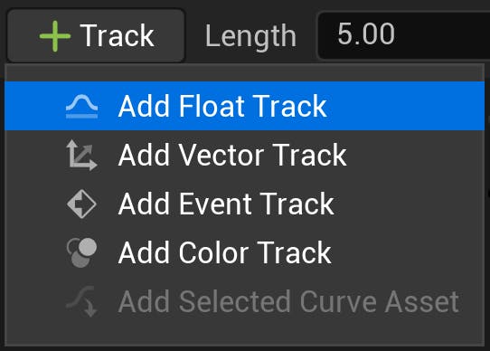
Give the resulting track a name. In this tutorial, the Float Track is called “Alpha”.
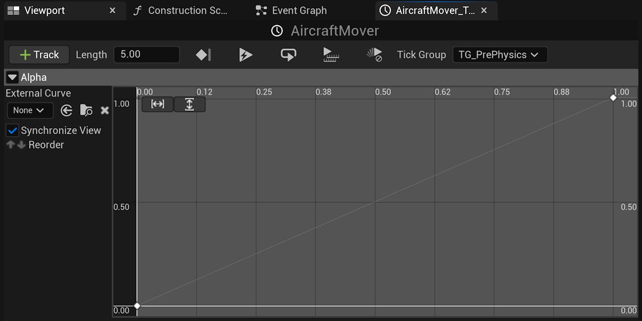
Add two keyframes to the timeline by right-clicking on the curve and selecting Add key to Curve. For the first keyframe, set the Time and Value to 0. For the second keyframe, set the Time and Value to 1. The final curve looks like this:
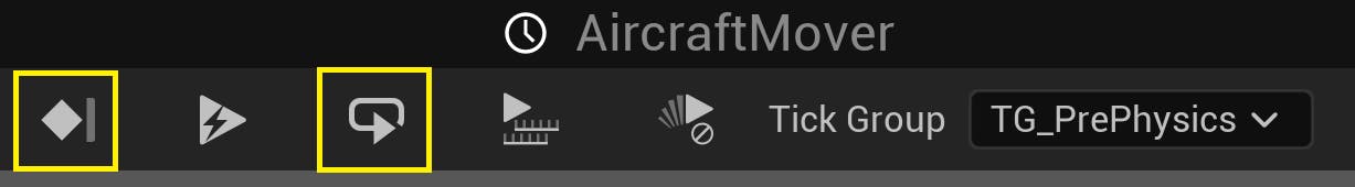
Make sure to enable Use Last Keyframe, which will be the leftmost icon on the toolbar. If you would like the flight to loop once it ends, click the Loop icon.
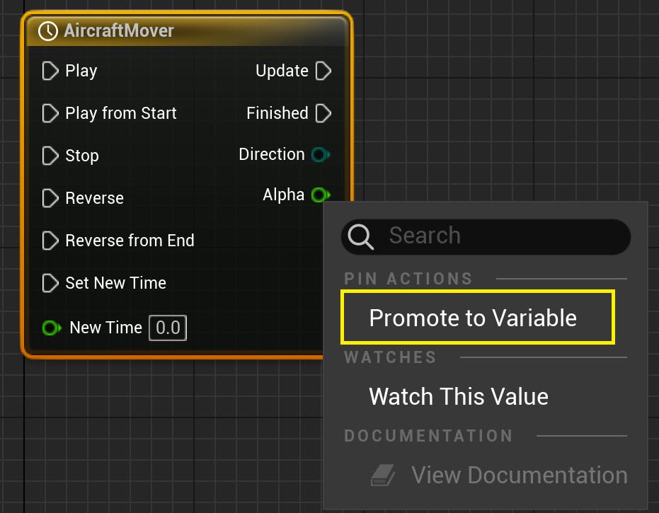
8Return to the Event Graph and promote the Alpha output pin of the Timeline node. Do this by right-clicking on the pin and selecting Promote to variable. This will add it to the Variables panel on the left of the editor.
9Add a variable called “Duration” to BP_Aircraft using the plus icon next to Variables. This variable will determine how long the aircraft takes to fly along the path. Make it a Float variable and then click on the eye symbol beside it. This will make it public and editable in the main Unreal Editor.
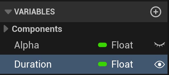
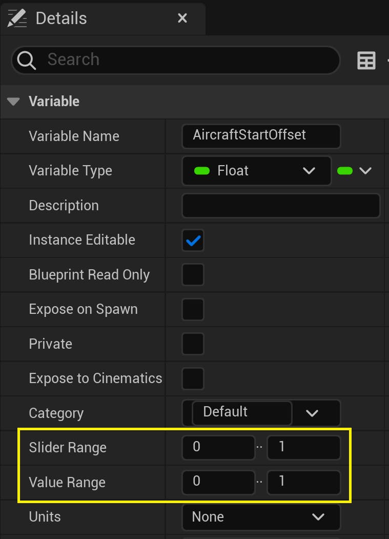
Next, add another Float variable named ”AircraftStartOffset” and make it public. This variable will be used to determine where on the timeline the flight begins.
With this variable selected, navigate to the Details panel in the Blueprint Editor. Set the Slider Range and Value Range values to 0 and 1, respectively, because the timeline goes between 0 and 1.
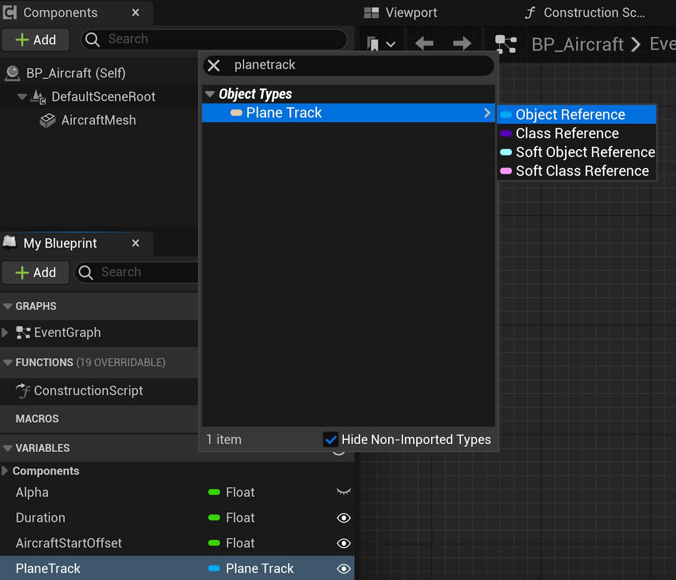
Finally, create a new variable with type PlaneTrack (Object Reference) and make it public. Name it "PlaneTrack" accordingly. This will be used to store a reference to PlaneTrack object and retrieve the positions on its spline.
10Complete the rest of the Move Aircraft custom event as follows:
Then compile the Blueprint.
11Next, you will add logic to connect the PlaneTrack spline to the Move Aircraft function and interpolate the position of the aircraft using the spline. In the same Event Graph, create the following node network below the Move Aircraft function:
12Lastly, connect the two Blueprint networks together with the Set Actor Transform node:
Compile the Blueprint.
13Navigate back to the main editor. Add your aircraft object to the scene, by either dragging and dropping the BP_Aircraft into the scene from the Content Browser or searching for “Aircraft” in the Place Actor panel.
14There are several ways to trigger the Move Aircraft event. In this tutorial, it's triggered by a key press.
Return to the Level Blueprint. In the Event Graph, add a Keyboard node (M is used here). Connect this Keyboard node to the Move Aircraft event as follows:
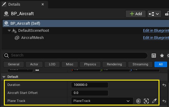
15With the BP_Aircraft actor selected, head to the Details panel and initialize the public variables Duration, PlaneTrack, and AirplaneOffset.
Note that with Duration, the higher the value, the longer it will take the aircraft to travel the path. For Duration, a value of 100,000 works well. You can modify the AirplaneOffset variable to start the flight at another point on the path. For example, because 0.0 is the start and 1.0 is the end, set AirplaneOffset to 0.9 to begin closer to the end of the flight.
16With the viewport focused on the aircraft, click Play and press M (or the key that you chose to connect the Move Aircraft event to) to start the flight.
Depending on the aircraft model you use, you may have to adjust its rotation to align with its movement along the spline. You can fix this by opening the BP_Aircraft Blueprint, clicking on AircraftMesh (the StaticMeshComponent), and adjusting the Rotation.
To enhance your project, you can implement camera switching to observe the flight from different points of view.
1Using the Place Actors panel, add two new Camera Actors to the scene. Name one of them “SideCamera” and the other “TopCamera”. Then, in the Outliner panel, drag and drop the actors under BP_Aircraft so that they become its children:
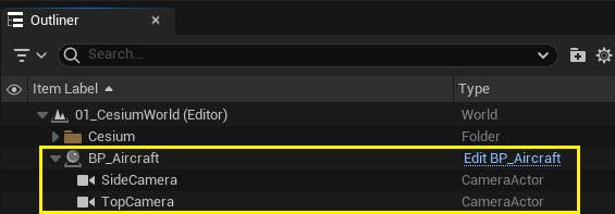
Now, when the aircraft moves, the cameras will move along with it.
2Adjust the cameras so that one is looking at the aircraft directly from the top and the other has a side view:

3Once the cameras are positioned, navigate to the Level Blueprint. Add custom keyboard events for the top and side camera views:
Compile the Blueprint and then return to the main editor to view the result. In Play mode, press the keys you specified in the Level Blueprint to test the new camera switching behavior.
PlaneTrack.h:
// Copyright 2020-2025 CesiumGS, Inc. and Contributors

#pragma once

#include "CoreMinimal.h"
#include "GameFramework/Actor.h"

#include "Components/SplineComponent.h"
#include "CesiumGeoreference.h"
#include "Engine/DataTable.h"

#include <CesiumGeospatial/Cartographic.h>
#include <CesiumGeospatial/Ellipsoid.h>

#include "PlaneTrack.generated.h"

USTRUCT(BlueprintType)
struct FAircraftRawData : public FTableRowBase
{
	GENERATED_USTRUCT_BODY()

public:
	FAircraftRawData()
		: Longitude(0.0)
		, Latitude(0.0)
		, Height(0.0)
	{
	}

	UPROPERTY(EditAnywhere, Category = "FlightTracker")
	double Longitude;
	UPROPERTY(EditAnywhere, Category = "FlightTracker")
	double Latitude;
	UPROPERTY(EditAnywhere, Category = "FlightTracker")
	double Height;
};

UCLASS()
class CESIUMFORUNREALSAMPLES_API APlaneTrack : public AActor
{
	GENERATED_BODY()

public:
	// Spline variable to represent the plane track
	UPROPERTY(BlueprintReadOnly, Category = "FlightTracker")
	USplineComponent* SplineTrack;

	// Cesium class that contain many useful  coordinate conversion functions
	UPROPERTY(EditAnywhere, Category = "FlightTracker")
	ACesiumGeoreference* CesiumGeoreference;

	// An Unreal Engine data table to store the raw flight data
	UPROPERTY(EditAnywhere, Category = "FlightTracker")
	UDataTable* AircraftsRawDataTable;

	// Sets default values for this actor's properties
	APlaneTrack();

protected:
	// Called when the game starts or when spawned
	virtual void BeginPlay() override;

public:
	// Called every frame
	virtual void Tick(float DeltaTime) override;

	// Function to parse the data table and create the spline track
	UFUNCTION(BlueprintCallable, Category = "FlightTracker")
	void LoadSplineTrackPoints();
};
PlaneTrack.cpp:
// Copyright 2020-2025 CesiumGS, Inc. and Contributors

#include "PlaneTrack.h"

// Sets default values
APlaneTrack::APlaneTrack()
{
	// Set this actor to call Tick() every frame.  You can turn this off to improve performance if you don't need it.
	PrimaryActorTick.bCanEverTick = true;

	// Initialize the track
	SplineTrack = CreateDefaultSubobject<USplineComponent>(TEXT("SplineTrack"));
	// This lets us visualize the spline in Play mode
	SplineTrack->SetDrawDebug(true);
	// Set the color of the spline
	SplineTrack->SetUnselectedSplineSegmentColor(FLinearColor(1.f, 0.f, 0.f));
}

// Called when the game starts or when spawned
void APlaneTrack::BeginPlay()
{
	Super::BeginPlay();
}

// Called every frame
void APlaneTrack::Tick(float DeltaTime)
{
	Super::Tick(DeltaTime);
}

void APlaneTrack::LoadSplineTrackPoints()
{
	if (this->AircraftsRawDataTable != nullptr && this->CesiumGeoreference != nullptr)
	{
		int32 PointIndex = 0;
		for (auto& row : this->AircraftsRawDataTable->GetRowMap())
		{
			FAircraftRawData* Point = (FAircraftRawData*)row.Value;
			// Get row data point in lat/long/alt and transform it into Unreal points
			double PointLatitude = Point->Latitude;
			double PointLongitude = Point->Longitude;
			double PointHeight = Point->Height;

			// Compute the position in UE coordinates
			FVector SplinePointPosition = this->CesiumGeoreference->TransformLongitudeLatitudeHeightPositionToUnreal(FVector(PointLongitude, PointLatitude, PointHeight));
			this->SplineTrack->AddSplinePointAtIndex(SplinePointPosition, PointIndex, ESplineCoordinateSpace::World, false);

			// Get the up vector at the position to orient the aircraft
			const CesiumGeospatial::Ellipsoid& Ellipsoid = CesiumGeospatial::Ellipsoid::WGS84;
			glm::dvec3 upVector = Ellipsoid.geodeticSurfaceNormal(CesiumGeospatial::Cartographic(FMath::DegreesToRadians(PointLongitude), FMath::DegreesToRadians(PointLatitude), FMath::DegreesToRadians(PointHeight)));

			// Compute the up vector at each point to correctly orient the plane
			FVector4 ecefUp(upVector.x, upVector.y, upVector.z, 0.0);
			FMatrix ecefToUnreal = this->CesiumGeoreference->ComputeEarthCenteredEarthFixedToUnrealTransformation();
			FVector4 unrealUp = ecefToUnreal.TransformFVector4(ecefUp);
			this->SplineTrack->SetUpVectorAtSplinePoint(PointIndex, FVector(unrealUp), ESplineCoordinateSpace::World, false);

			PointIndex++;
		}
		this->SplineTrack->UpdateSpline();
	}
}
Currently, the aircraft’s velocity is constant throughout the path. If your dataset has velocity or speed variable, you can use it to adjust the velocity of the aircraft depending on its position on the spline track. Similarly, you can adjust the heading, yaw, and pitch of the aircraft with real-world data.
Visit the community forum to share your feedback on Cesium for Unreal and the tutorials, or tag Cesium on LinkedIn to show the world what you’ve built.