Tour of the New glTF Architecture in CesiumJS
CesiumJS and glTF have a long history together. CesiumJS had one of the first glTF loaders back in 2012 when glTF was known as WebGLTF.
A lot has happened since then: glTF 1.0 was released, glTF 1.0 embedded shaders became glTF 2.0 PBR materials, and the extension ecosystem grew rapidly. More recently, 3D Tiles Next introduced glTF extensions for encoding metadata at per-texel granularity and allowed tilesets to reference glTF directly. Over the years we’ve learned how the community uses glTF and 3D Tiles in practice, and now we’re using this knowledge to inform the future of CesiumJS.
We got a lot of mileage out of our original glTF loader, but we had started to outgrow it. So we embarked on a complete redesign with several goals in mind:
- Decouple glTF loading from model rendering
- Add support for metadata at per-vertex and per-texel granularity
- Make shader generation extensible and support custom shaders
- Cache textures to reduce memory usage when textures are shared across models
- Create a cleaner integration with 3D Tiles formats such as .pnts point clouds
- Improve or at least maintain loading and rendering performance
Though the public API for Model, Cesium’s glTF loader, hasn’t changed, the internal structure looks quite a bit different.
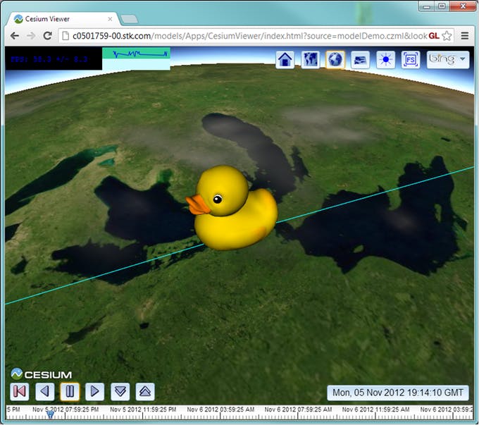
The famous COLLADA duck model, converted to glTF and placed in the orbit of the International Space Station around Earth, circa 2012.
Loading a glTF model
Model separates its loading and parsing code into a number of classes for resource loading, starting with the GltfLoader class. This class is responsible for fetching a .glb or .glTF file, along with any external resources like binary buffers or images. The resulting glTF JSON is parsed and converted into an in-memory representation called ModelComponents. This object is structured similarly to the JSON, but many properties are converted into their corresponding CesiumJS objects. For example, textures are converted into Texture instances. There are also several functions and classes for parsing metadata from the EXT_mesh_features and EXT_structural_metadata extensions introduced with 3D Tiles Next.
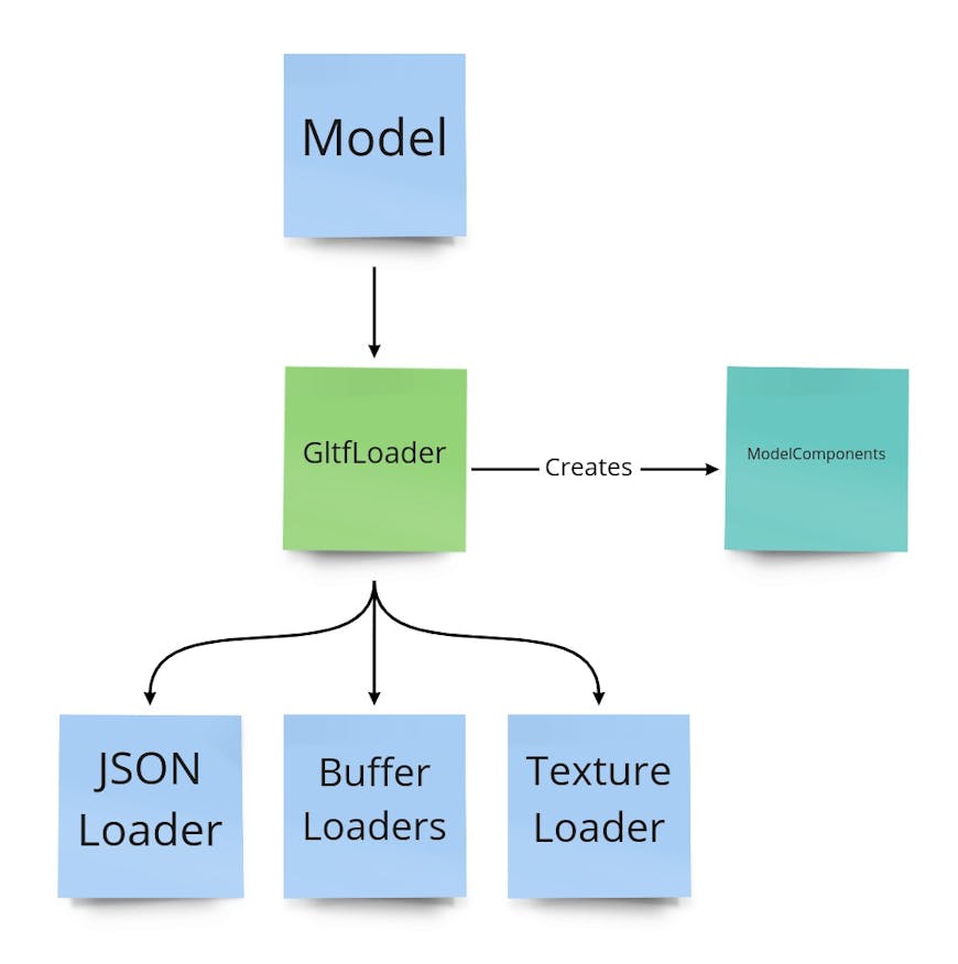
GltfLoader parses the glTF file and produces the in-memory representation, ModelComponents. GltfLoader uses several other loaders for smaller tasks, such as loading textures or uploading vertex buffers to the GPU.
glTF allows sharing resources to reduce storage space, bandwidth, and processing time. This can happen at many levels of abstraction. For example, two primitives in a glTF file may share the same buffer for geometry while using different materials. Or two different glTF files may reference the same external image for their textures. At runtime, the same glTF may be rendered at multiple locations in a scene. In all these cases, the data only needs to be loaded once and reused.
Model uses a global ResourceCache to store resources that can be shared, such as textures, binary buffers, and the JSON portion of glTF files. When the loading code needs a resource, first the cache is checked. On a cache hit, the reference count is incremented and the resource is returned. Only on a cache miss is the resource loaded into memory. Whether the resource is shared within the glTF, between multiple glTFs, or between multiple copies of the same glTF, the resource is loaded into memory only once.
This caching is especially helpful for loading 3D Tiles tilesets that share the same textures across many tiles. The previous glTF implementation did not have a global cache for textures, so the new implementation can significantly reduce memory usage in such cases.

In this San Diego 3D Tiles dataset, memory usage goes from 564 MB to 344 MB when using Model thanks to the global texture cache.
Even after caching, very large scenes still require loading many external resources. To ensure data is streamed as efficiently as possible, CesiumJS makes network requests in parallel up to the browser limits.
Rendering a model: shader-first design
Our new loading architecture allows for much more flexibility, and we wanted our new rendering method to be equally flexible. Rendering a glTF model is a complex task. The glTF specification allows for a variety of materials and for other functionality, such as animation. Furthermore, CesiumJS adds many runtime features such as picking, styling, and custom GLSL shaders. We needed a design that handles all these details in a maintainable way.
The most complex part of preparing a model for rendering is generating the GLSL shader program, so we examined this carefully from the start. In 3D graphics, there are two common approaches to generating complex shaders.
First is the uber shader, where all the shader variations are written in one large GLSL file, and different preprocessor definitions are used to select which portions of the code run at compile time. The GLSL code can be stored in a separate file, decoupling it from the runtime JavaScript code. This works nicely when the shader variations are known in advance. For example, all glTF materials follow the same physically-based rendering (PBR) algorithm. The main difference is determining which textures and other uniforms to enable based on the glTF material settings.
For example, some models use materials with textures; others use constant diffuse colors. See the following example, a simplified excerpt of MaterialStageFS.glsl:
vec4 baseColorWithAlpha = vec4(1.0);
#ifdef HAS_BASE_COLOR_TEXTURE
baseColorWithAlpha = texture2D(u_baseColorTexture, baseColorTexCoords).rgb;
#elif HAS_BASE_COLOR_FACTOR
baseColorWithAlpha = u_baseColorFactor.rgb;
#endif


float occlusion = 1.0;
#ifdef HAS_OCCLUSION_TEXTURE
occlusion = texture2D(u_occlusionTexture, occlusionTexCoords).r;
#endif
Another method is to dynamically generate lines of the shader at runtime. This is sometimes necessary when there are a variable number of attributes. For example, when skinning to a model, the number of weights and joint matrices depends on the data in the glTF. Dynamic code generation allows for more advanced shader logic than #ifdef can provide. However, it can also lead to lots of interleaved GLSL and JavaScript code, which can be hard to read. Thus, any dynamic code generation should be done with care to keep it maintainable. The snippet below is an excerpt from the old implementation’s processPbrMaterials.js:
  if (hasNormals) {
    techniqueAttributes.a_normal = {
      semantic: "NORMAL",
    };
    vertexShader += "attribute vec3 a_normal;\n";
    if (!isUnlit) {
      vertexShader += "varying vec3 v_normal;\n";
      if (hasSkinning) {
        vertexShaderMain +=
          "    v_normal = u_normalMatrix * mat3(skinMatrix) * weightedNormal;\n";
      } else {
        vertexShaderMain += "    v_normal = u_normalMatrix * weightedNormal;\n";
      }
      fragmentShader += "varying vec3 v_normal;\n";
    }
    fragmentShader += "varying vec3 v_positionEC;\n";
  }
For the new Model architecture, we wanted to create a hybrid of the two options. We divided up each shader into a sequence of logical steps called pipeline stages. Each pipeline stage is a function that can be called from the main() function. Some stages can be enabled or disabled via #define directives, but the order of the steps in the shader is fixed. This means that the main() function is a good candidate for the uber shader approach. Below is a simplified excerpt from ModelFS.glsl:
void main() {
  // Material colors and other settings to pass through the pipelines
  czm_modelMaterial material = defaultModelMaterial();


  // Process varyings and store them in a struct for any stage that needs
  // attribute values.
  ProcessedAttributes attributes;
  geometryStage(attributes);

  // Sample textures and configure the material
  materialStage(material, attributes);

  // If a style was applied, apply the style color
  #ifdef HAS_CPU_STYLE
  cpuStylingStage(material, selectedFeature);
  #endif

  // If the user provided a CustomShader, run this GLSL code.
  #ifdef HAS_CUSTOM_FRAGMENT_SHADER
  customShaderStage(material, attributes);
  #endif


  // The lighting stage always runs. It either does PBR shading when LIGHTING_PBR
  // is defined, or unlit shading when LIGHTING_UNLIT is defined.
  lightingStage(material);

  // Handle alpha blending
  gl_FragColor = handleAlpha(material.diffuse, material.alpha);
}
The individual pipeline stages in the shader may use either an uber shader or dynamic code generation; whichever is more appropriate. For example, the material pipeline stage uses an uber shader since glTF materials use a fixed set of possible textures and uniforms (see MaterialStageFS.glsl). Other pipeline stages like the feature ID pipeline stage must dynamically generate function bodies depending on how many attributes/textures are provided in a particular glTF. For example, here is an excerpt of GLSL code generated when the 3D Tiles Next Photogrammetry Sandcastle is run:
// This model has one set of texture coordinates. Other models may have 0 or more of them.
void setDynamicVaryings(inout ProcessedAttributes attributes) {
    attributes.texCoord_0 = v_texCoord_0;
}

// This model has 2 feature ID textures, so two lines of code are generated.
// Other models might store feature IDs in attributes rather than textures so different code
// would be generated.
void initializeFeatureIds(out FeatureIds featureIds, ProcessedAttributes attributes) {
    featureIds.featureId_0 = czm_unpackUint(texture2D(u_featureIdTexture_0, v_texCoord_0).r);
    featureIds.featureId_1 = czm_unpackUint(texture2D(u_featureIdTexture_1, v_texCoord_0).r);
}

Screenshot from the photogrammetry classification example mentioned above.
With the new GLSL shader design, we’re able to better accommodate the many different scenarios users bring to CesiumJS. And the new design is more modular, as each pipeline stage is its own function, so new stages can be defined easily as we add new functionality. Furthermore, much of the GLSL code is stored in separate .glsl files (see the Shaders/Model/ folder), decoupled from the JavaScript code.
The model rendering pipeline
The JavaScript code that prepares a model for rendering in CesiumJS closely mirrors the pipeline structure of the model shader. The pipeline stages are formalized as JavaScript modules with the naming convention XxxPipelineStage. The input and output of the pipeline are render resources, a bundle of GPU resources and settings that are needed to prepare the primitive for rendering. Render resources include many properties, most notably:
- A
ShaderBuilderinstance - this is a helper object that can build a GLSL shader program incrementally. - An array of vertex attribute buffers
- A uniform map - a collection of callback functions to set shader uniform values
- WebGL flags for configuring render settings such as depth testing or backface culling
Most JavaScript pipeline stages will define a corresponding GLSL pipeline stage function in the vertex shader (e.g., `DequantizationPipelineStage.js`), in the fragment shader (e.g., `LightingPipelineStage.js`), or both (e.g., `GeometryPipelineStage.js`). However, this is not a requirement. Some JS pipeline stages modify other parts of the render resource (e.g., `AlphaPipelineStage.js`).
The goal of the pipeline is to produce draw commands that can be sent to CesiumJS’s rendering engine. To learn more about how CesiumJS renders a frame, see this blog post. The algorithm for creating the draw commands is as follows:
- Configure the pipeline for the primitive. Populate an array with only the relevant pipeline stages, the others can be skipped. See
ModelRuntimePrimitive.configurePipeline() - Create an empty render resources object.
- Execute the pipeline. Pass the render resources into each stage in the array, and it will be modified in place.
- Now that the render resources are configured, create a
ModelDrawCommandinstance for this primitive. - Each frame, call
ModelDrawCommand.pushCommands()to push the appropriate draw command(s) to frameState.commandList. ModelDrawCommand automatically handles 2D, translucent, silhouette, and other derived commands.
For the full code that builds and executes the pipeline, see ModelSceneGraph.buildDrawCommands().
Example pipelines
Let’s take a look at some of these pipeline stages in more detail. First, let’s consider an unlit, textured model. This is one of the simplest situations for rendering, so the pipeline consists of just a few stages.
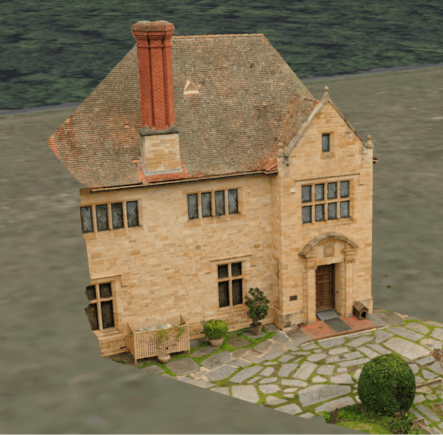
An example of a textured photogrammetry model of a building. The lighting was prebaked in the base color texture, so the model is rendered as unlit.
- GeometryPipelineStage:
- JavaScript: Adds the primitive’s vertex attributes to the draw command’s vertex array. It also adds the
geometryStage()function to both the vertex and fragment shaders. - Vertex Shader: Transforms positions and normals from model coordinates to view coordinates to set varyings. Also converts the position to clip coordinates for computing
gl_Position - Fragment Shader: Normalizes the interpolated normals
- JavaScript: Adds the primitive’s vertex attributes to the draw command’s vertex array. It also adds the
- MaterialPipelineStage:
- JavaScript: Adds the
materialStage()function to the fragment shader, defines a uniform for the base color texture, sets theHAS_BASE_COLOR_TEXTUREdefine in the fragment shader, and sets the lighting model toUNLIT - Fragment Shader: Samples color from the base color texture and stores this color in a material struct that will be passed to the lighting pipeline stage
- JavaScript: Adds the
- LightingPipelineStage:
- JavaScript: Adds the
lightingStage()function to the fragment shader and definesLIGHTING_UNLITin the fragment shader. - Fragment Shader: Takes the material struct from the material stage and applies lighting. In this case, unlit lighting returns the unmodified diffuse color. If the model used physically based rendering (PBR) materials, this stage would apply the lighting equations as described in the glTF specification.
- JavaScript: Adds the
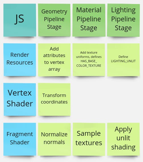
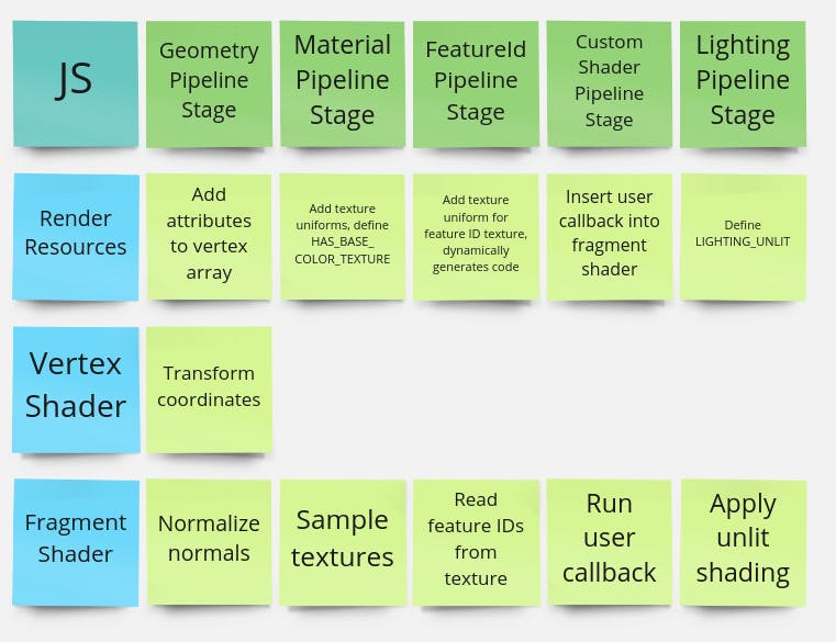
Diagram of the example pipeline described above. Every pipeline stage has JavaScript code to update the render resources. Most pipeline stages add a function to the vertex shader, the fragment shader, or both where relevant.
Now, let’s look at a more involved example that uses new functionality. Let’s add per-texel classification via the new EXT_mesh_features extension. We’ll also add a CustomShader to visualize the classification with code similar to the following:
model.customShader = new Cesium.CustomShader({
  fragmentShaderText: `
  #define ROOF 0
  #define WALL 1
  void fragmentMain(FragmentInput fsInput, inout czm_modelMaterial material) {
    int featureId = fsInput.featureIds.featureId_0;
    if (featureId == ROOF) {
      material.diffuse *= vec3(1.0, 1.0, 0.0);
    } else if (featureId == WALL) {
      material.diffuse *= vec4(0.0, 1.0, 1.0);
    }
    // …and similar for other features.
  }
  `
});
The end result looks like this:
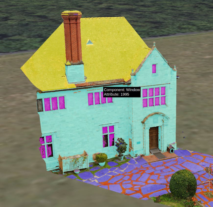
The final result after applying the CustomShader to highlight features in different colors.
Given all of the above features, the model rendering pipeline will be as follows:
- GeometryPipelineStage: Same as in previous example
- MaterialPipelineStage: Same as in previous example
- FeatureIdPipelineStage:
- JavaScript: Dynamically generates fragment shader code needed to gather all feature IDs into a single struct called
FeatureIds. In this case, there is only a single feature ID texture to process. In other situations, feature IDs may be stored in vertex attributes instead. - FragmentShader: The dynamically generated code reads the feature ID values from the texture and stores them in the
FeatureIdsstruct.
- JavaScript: Dynamically generates fragment shader code needed to gather all feature IDs into a single struct called
- CustomShaderPipelineStage:
- JavaScript: Examines the
CustomShaderand determines how to update the vertex shader, fragment shader, and uniform map as needed. In this example, it adds the user-definedfragmentMain()callback to the fragment shader. - Fragment Shader:
customShaderStage()is a wrapper function that gathers the input parameters and material and callsfragmentMain(fsInput, material). This modifies the material before it reaches the lighting stage.
- JavaScript: Examines the
- LightingPipelineStage: Same as in previous example
The pipeline for the second example includes two additional stages, one for processing feature Ids and another for adding the CustomShader.
There are several other pipeline stages beyond the ones listed above. Some implement glTF extensions like instancing and mesh quantization, and others provide CesiumJS-specific functionality like point cloud attenuation and clipping planes. The modular design of these pipeline stages makes it easy to add new functionality into the rendering pipeline.
3D Tiles integration
Not only did this redesign allow us to modernize our approach to rendering glTF models in CesiumJS, but it also gave us the opportunity to simplify how the 3D Tiles and glTF systems work together.
In 3D Tiles, each tileset contains a spatial tree of tiles, and each tile may contain a content file. In 3D Tiles 1.0, the Batched 3D Model (.b3dm) format was a wrapper around a glTF asset that added a batch table containing per-feature metadata. The Instanced 3D Model (.i3dm) format contained a glTF asset and a list of instance transforms. In CesiumJS, the implementation for these two formats consisted of two Cesium3DTileContent subclasses that both used the old Model class. Meanwhile, the Point Cloud (.pnts) format did not use glTF, so it had a separate code path.
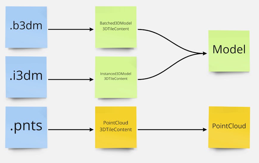
In 3D Tiles 1.0, glTF files were not directly referenced. Furthermore, point clouds were implemented differently from other model types.
In 3D Tiles Next, tilesets may now use glTF assets (.gltf/.glb files) as tile content directly. The old tile formats are now representable as glTF assets plus extensions. .b3dm files become a glTF with the EXT_structural_metadata extension to store metadata analogous to the old batch table. .i3dm files use EXT_mesh_gpu_instancing for instancing and EXT_structural_metadata for the batch table. Even .pnts can be expressed as a glTF model with the POINTS primitive mode.
Using glTF assets directly as tile content simplifies the CesiumJS implementation. There are multiple model loaders, but the runtime details are all handled by a single Model.
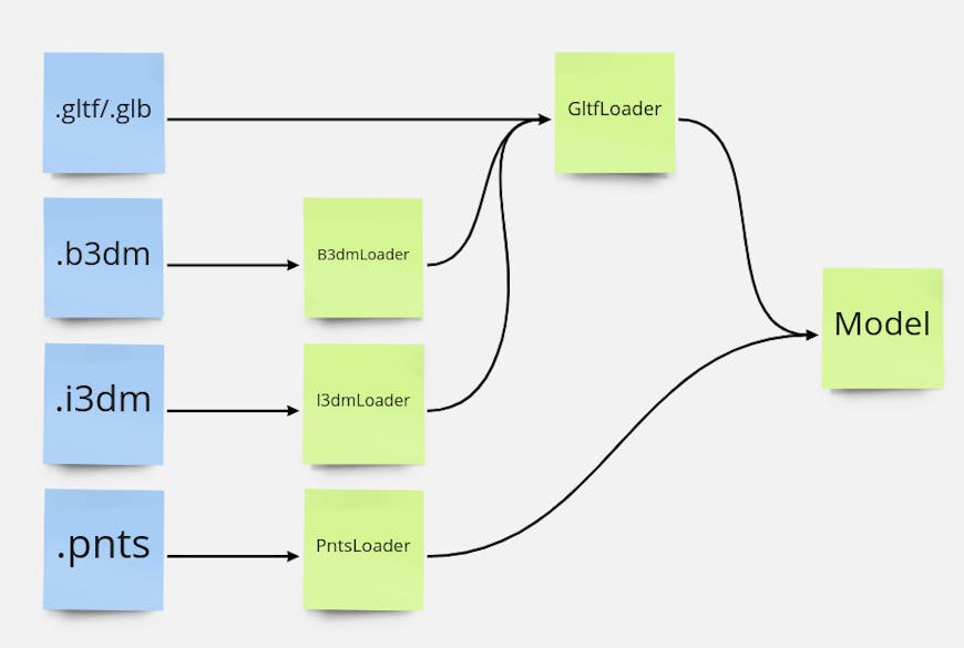
glTF content can be used directly with Model. All 3D Tiles 1.0 formats can be transcoded to Model at runtime.
Aside from simplifying the code, this new architecture provides a more consistent experience when using 3D Tiles. For example, custom shaders work for all content types.
Try it yourself
The new Model architecture has been available since the 1.97 release in September. See the 3D Models Sandcastle for a simple example. To try some of the new features like CustomShader, see the CustomShader Model Sandcastle, and other Sandcastles from the 3D Tiles Next tab.