Introducing CAD-Style Workflow Extensions for glTF and 3D Tiles 2.0
As Cesium and Bentley Systems have come together to build the comprehensive open platform for the built and natural environment, we’re pairing Bentley’s deep AEC experience with interoperability to serve the community. To bring CAD-style visualization concepts to CesiumJS, our team has built a set of AEC workflow extensions to glTF, the open standard foundational to the new 3D Tiles 2.0.
CAD users expect specific—yet common and well-established—visualization requirements, including crisp hard edges and silhouettes, lines drawn with precise widths and dash patterns, points sized to convey semantics, textures that hold a consistent on-screen scale at any zoom, and planar fills with well-defined depth and masking behavior. These are standard features in tools like Bentley’s MicroStation and other engineering design environments, and now they are coming to CesiumJS and Cesium for Unreal. Many have already shipped and others are landing soon.
Edge display
Infrastructure engineers often want non-photorealistic visualizations of their designs. In CAD-oriented workflows, visualization of the edges of a surface can be as important as visualization of the surface itself. CesiumJS now supports loading and rendering CAD-style edges.
To accomplish this, we devised new glTF specifications EXT_mesh_primitive_restart and EXT_mesh_primitive_edge_visibility which extend the 3D Tiles format such that edge geometry can be properly embedded inside design model tilesets.
Powered by these extensions, CesiumJS can now render surfaces with edges superimposed alongside the surfaces and just the edges (no surfaces).
Experiment with edge display in this Sandcastle.
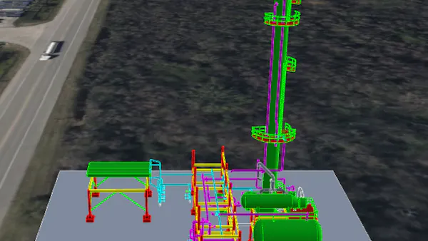
Visible edges rendering in CesiumJS alongside surfaces.
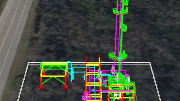
A CAD model rendered in CesiumJS with visible edges drawn without any surfaces (wireframe style).
The edge visibility extension encodes one edge type per triangle edge:
hiddenis never drawn.silhouetteis drawn only when one adjacent triangle faces the camera and the other faces away.hardis always drawn and represents a real sharp edge or boundary.repeated hardmarks shared hard edges without duplicating them.
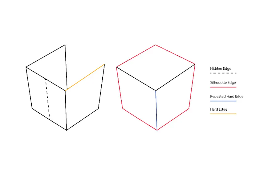
Edge classifications encoded by the extension: hidden edges are never drawn, hard edges are always drawn, and silhouette edges are drawn only when one adjacent triangle faces the camera and the other faces away.
The edge visibility extension also supports edge-level materials and connected edge strings:
materialsdefines edge materials separate from triangle surfaces or primitives, so edge appearance can be controlled independently.lineStringsdefines connected edge segments using primitive restart (EXT_mesh_primitive_restart) for continuous outlines or edges needing different materials.
CesiumJS introduces a dedicated edge rendering pass that decodes this visibility data, reconstructs the edges as quad-based geometry (to guarantee stable screen space widths across browsers and GPUs), and integrates them with the main surface pass using feature ID and depth comparisons to avoid z-fighting.
For more information, check out these PRs:
Line and point styling
CAD workflows often rely on line and point appearance to convey semantics. Line thickness and dash patterns are commonly used to differentiate boundaries, annotations, or feature classes. Point color and size can be used to highlight survey markers, control points, or other features. To accomplish this, we introduced new glTF extensions BENTLEY_materials_line_style and BENTLEY_materials_point_style, which extend the 3D Tiles format such that glTF-embedded lines and points can be styled for design model tilesets, both of which are now supported in CesiumJS.
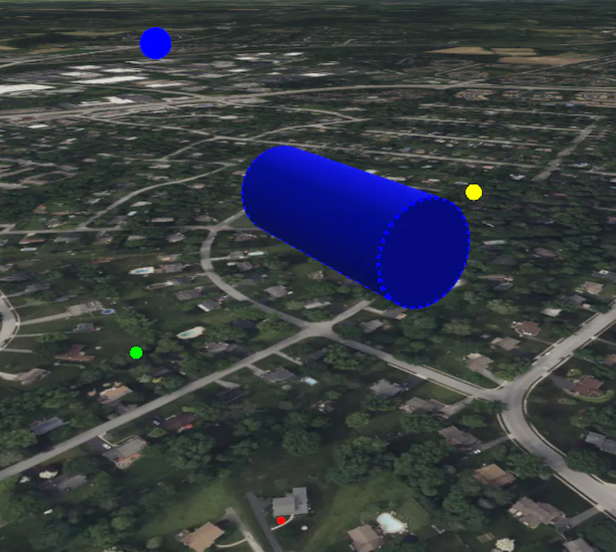
CesiumJS rendering edges with width and dash pattern and colorized points with a variety of diameters.
Line styling applied to edges
Line styling naturally works well with EXT_mesh_primitive_edge_visibility. Edge visibility determines which edges are drawn, while line styling determines how those edges appear. Used together, edges can achieve unique styling.
Line and point properties
The line styling extension adds two properties to a glTF material, which apply to any line primitive or visible edge that references the material:
- width defines the thickness of the line in screen pixels, ensuring visual consistency regardless of camera distance or world scale.
- pattern defines a repeating on/off dash pattern encoded as a 16-bit unsigned integer, where each bit corresponds to one screen pixel along the line. This is compact, GPU friendly, and expressive enough to cover common CAD line styles, such as solid, dashed, and dotted lines.
In the case of points, a single styling property is specified (color can be inferred from the material itself):
- diameter is the diameter of each point in CSS pixels.
Constant level of detail (LOD) textures
In many engineering and geospatial workflows, textures are used to convey representative surface detail. This can include patterns on terrain, hatching on facades, or material finishes on infrastructure. With standard UV-based texture mapping, however, those patterns don’t remain consistent across different viewing scales. Textures visually shrink as the camera zooms out and grow as it zooms in, making fine detail disappear at distance and appear unnaturally coarse up close.
We have introduced the glTF extension EXT_textureInfo_constant_lod to support texture consistency. Using this extension, CesiumJS provides a constant LOD texture coordinate generation technique. Rather than relying on baked-in UVs, texture coordinates are computed dynamically each frame to maintain a roughly constant texel-to-pixel ratio on screen as the camera moves. Adjacent scale levels are smoothly blended so transitions between LODs do not appear sudden.

With EXT_textureInfo_constant_lod support in CesiumJS, the texture maintains a roughly constant on-screen scale as the camera zooms, with adjacent LOD levels smoothly blended.

With EXT_textureInfo_constant_lod support in CesiumJS, the texture maintains a roughly constant on-screen scale as the camera zooms, with adjacent LOD levels smoothly blended.
Authoring considerations
For the effect to look correct, glTF files need to be authored with the extension in mind. Textures should be designed to tile seamlessly, since they will repeat across surfaces at varying scales. The values baked into the extension must be chosen to match the real-world scale of the model and the expected viewing distances. This includes how often the texture repeats per meter, its offset, and the distance over which the LOD blending applies.
Planar fill
Planar polygons with filled interiors are fundamental elements in many CAD workflows, where the appearance of a polygon’s interior fill can convey meaning beyond just a flat color. A filled region may need to mask out geometry behind it, sit behind a coplanar hatch pattern or text annotation, or be toggled on and off in a wireframe view. For example, a designer may superimpose some lettering as a label on a wall, expecting that the label always appears on top of the wall and be readable without any interference from the underlying wall geometry. The team created the BENTLEY_materials_planar_fill extension to support these sorts of behaviors as material-level properties within glTF.
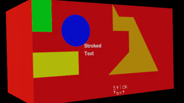
With BENTLEY_materials_planar_fill support in CesiumJS, the textured text (non-lines) and planar polygons exhibit no Z-fighting even though they are coplanar with the red surface (first image).
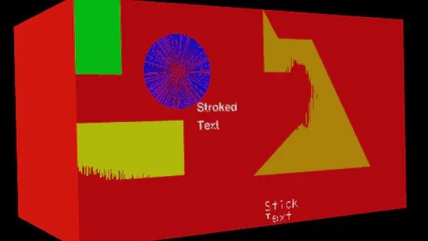
With BENTLEY_materials_planar_fill support in CesiumJS, the textured text (non-lines) and planar polygons exhibit no Z-fighting even though they are coplanar with the red surface (first image).
The extension is applied to a glTF material and signals two things to CesiumJS. First, it indicates that any primitive using the material is planar, so the engine can apply appropriate depth sorting. This ensures associated edges are in front of fills and planar primitives are in front of overlapping nonplanar ones. Second, it exposes a small set of properties that customize how the fill is drawn:
wireframeFillcontrols if the fill is shown in a wireframe view (never, always, or only when the user has toggled fill display on).backgroundFillcauses the fill to be drawn using the view’s background color, which is useful for creating an “invisible” polygon that masks out geometry behind it.- behind causes the fill to be drawn behind other coplanar geometry that belongs to the same logical object, mitigating z-fighting in cases like hatch patterns over a filled polygon, text inside a filled rectangle, or line work overlaying a solid surface.
Together, these properties give CAD applications a compact, material-driven way to describe the desired fill behaviors in CesiumJS.
Support for BENTLEY_materials_planar_fill is upcoming in CesiumJS.
Conclusion
By bringing these AEC extensions to glTF as part of 3D Tiles 2.0 and into CesiumJS, Cesium and Bentley want to empower the community with open, interoperable, best-in-class technology, benefiting the entire 3D geospatial ecosystem.
Your input and use cases are what guide our work. Try the Sandcastle and share your feedback on the forum.