Large Polygons in CesiumJS
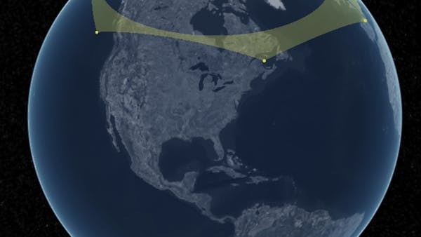
3D geospatial data is frequently augmented with vector data, like points, lines, and polygons, to enhance understanding. For example, a polygon can represent a building footprint or a swath of satellite coverage. Some of these polygons can become particularly large and even encircle the entire globe.
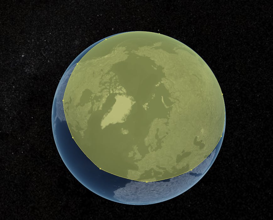
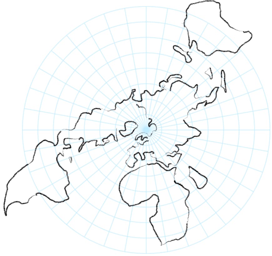
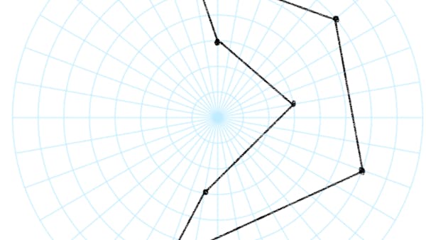
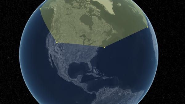
A large polygon around the North Pole rendered in CesiumJS.
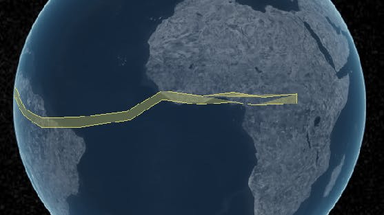
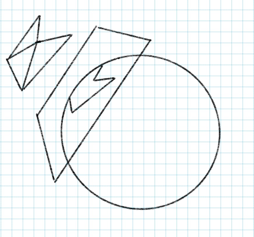
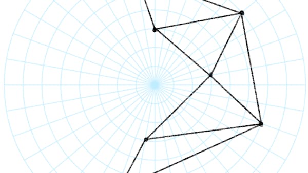
Before: an incorrect polygon triangulation rendered in CesiumJS. Note that the polygon wraps around the entire world and has an unexpected hole.
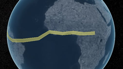
After: the correct polygon triangulation rendered in CesiumJS. 🎉
Polygons that approached this scale were sometimes seeing strange visual artifacts. Something in our polygon rendering pipeline was going amiss. So what's so special about big polygons on a 3D globe?
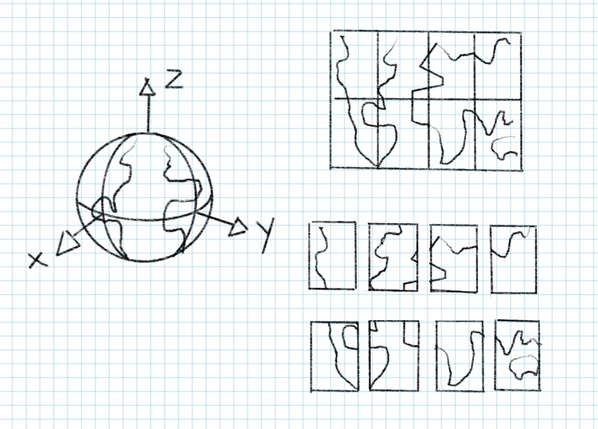
To render any geometry, we must break it down into triangles to create a mesh. The process to break an arbitrary simple polygon into triangles has been well defined in 2D. In CesiumJS, we use a library called earcut, which is fast enough for real-time triangulation in the browser.
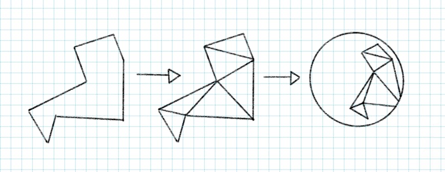
Polygons in CesiumJS are triangulated using the earclipping algorithm to be displayed in 3D on the ellipsoid surface.
We must first project the polygon positions to 2D. Previously, we would always project the polygon vertices onto a plane tangent to the ellipsoid. This worked great for polygons that did not span a large extent around the globe, as the projection produced little distortion when near the point of tangency.
Projecting a polygon on an ellipsoid surface to an ellipsoid tangent plane, where it is triangulated in a 2D coordinate system.
But it's not possible to project all points on an ellipsoid or sphere to a single plane. As you get farther from the point of tangency, there is more distortion. For extents of more than 180 degrees, the projection to a tangent plane always produces incorrect results, as positions "wrapped back" on themselves when viewed in 2D.
One straightforward solution would be to use multiple tangent planes instead of just one. To ensure a seamless mesh, a polygon must be split along the edge of each projected area.
From a performance standpoint, splitting polygons can be an expensive operation at the time of geometry creation, as the algorithm operates on each polygon edge and for each splitting plane. However, once triangulated, any split polygons are recombined later in the pipeline as part of the geometry batching step to ensure the same rendering performance as before.
Based on the polygon’s extent, we can save time by performing splitting operations only when we know it’s large enough. But for each time we project to a different space, the more times we’ll need to run through the splitting algorithm and the more the penalty there will be on runtime performance.
Even assuming an extent of no larger than 90 degrees, we would need to split a polygon a maximum of three times: on the x-axis, y-axis, and z-axis.
Splitting the ellipsoid into eight extents along the x-axis, y-axis, and z-axis.
Maybe the cartesian coordinate system is limiting us here. What about a different projection? For instance, cubemaps are a well-known way of projecting a 3D sphere to a 2D space for rendering skyboxes or environment maps.
The problem here is that not all projections are conformal; they do not properly preserve shape or the relative angles between the points. Although they can commonly distort area (which is why this type of projection is not commonly seen for mapping outside of polar regions), preserving shape is crucial for the geometric operations we perform on polygons. We rely on shape not only for the accuracy of triangulation but also for any clipping operations, determining winding order, or tests if the poles lie inside or outside the polygon.
A conformal map projection preserves shapes, but at the cost of distorting area.
One projection in particular had very few locations which would require splitting a polygon. Stereographic, or polar, 3D cartesian points can be projected from the South Pole to a plane tangent to the North Pole, or vice versa.
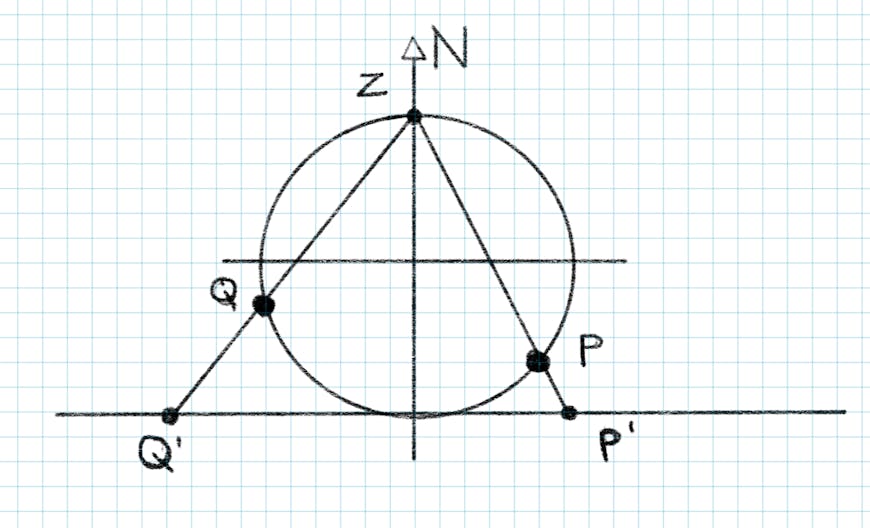
A stereographic projection of positions Q and P from the North Pole onto a plane at the South Pole.
The catch is that, because of precision issues with trigonometric functions at small angles, these projections are valid only for a little greater than one hemisphere. To handle this, we split polygons at the equator, making sure to handle the correct arc type for each edge. We need to perform only one split operation on the plane where z = 0.
Creating a triangulation in stereographic coordinates ensures angles between each of the polygon’s positions are preserved, even if the polygon wraps around the ellipsoid.
Creating a triangulation in stereographic coordinates ensures angles between each of the polygon’s positions are preserved, even if the polygon wraps around the ellipsoid.
Using stereographic coordinates also allows us to do many operations that would be tricky on a sphere with "simple" vector math. For example, we can now determine whether a pole lies inside or outside a polygon based on the sum of the angles of the polygon relative to the origin, and we can generate the correct cartographic bounds for the polygon.
Checking if a pole lies inside or outside a polygon is important for determining the correct cartographic bounding rectangle.
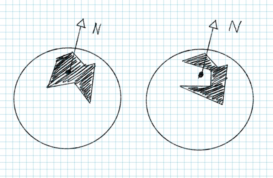
Before: an incorrect polar polygon ground primitive.
After: the correctly rendered polygon ground primitive.
If you have datasets with larger polygons, give them a try in the most recent version of CesiumJS!