Robust Polyline Rendering with WebGL
Rendering with Line Primitives
We ran into a few problems when using line primitives (LINES, LINE_STRIP, or LINE_LOOP) to render lines. First, the maximum line width when using ANGLE is 1.0. Second, drawing line primitives with lineWidth (without ANGLE) does not join line segments at a shared vertex:
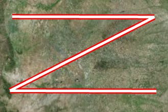
The image below shows lines with the two joins mitered:

Finally, our method to draw outlined lines without z-fighting was to use three passes with the stencil buffer.
Our Method
Our new method for drawing polylines is to draw a screen-aligned quads for each segment of the line. In WebGL, we do not have geometry shaders, so we duplicate each position of the line and extrude them in screen space in the vertex shader. To extrude the positions, we need to know the positions of adjacent vertices. Again, we do not have geometry shaders so we need to create additional vertex attributes for the adjacent position information.
Once we have the adjacent vertex positions and two vertices at the same position, we can extrude the positions in the directions normal to the line. If this is done to all of the vertex positions, we would end up with something similar to drawing line primitives with lineWidth without ANGLE image above. That is fine for the end points of the polyline, but we want to join the points where the segments of the polyline are connected. To find the direction to extrude the position, transform all of the positions to window coordinates and find half the sum of the two vectors pointing from the adjacent positions to the vertex position. The amount to move the vertex position in that direction will involve some trigonometry and will be discussed later in the post.
At first, we tried to keep the number of vertex attributes under 8 because that is the minimum needed to support WebGL. For each position, we need four vec3s. Two are used for the position in 3D and two are used for the position in 2D. The need for the position in two different modes is unique to Cesium. The reason we need two vec3s for a single 3D position is emulated double precision in the vertex shader. For more on that topic see, Precisions, Precisions.
To include each vertex position plus both adjacent vertex positions, we would need at least 12 vertex attributes. One way to keep the number of vertex attributes to 8, was to use only the directions from the current vertex to the adjacent vertices. We would need directions for both 3D and 2D. That still leaves us with four vec3s for the directions and a total of 8 vertex attributes. We would like to include more information in other vertex attributes such as texture coordinates, width, etc. We could further reduce the number of attributes by compressing the unit vector directions. This will take us to two vec4s for the direction. The method for compressing them will be described later in the post.
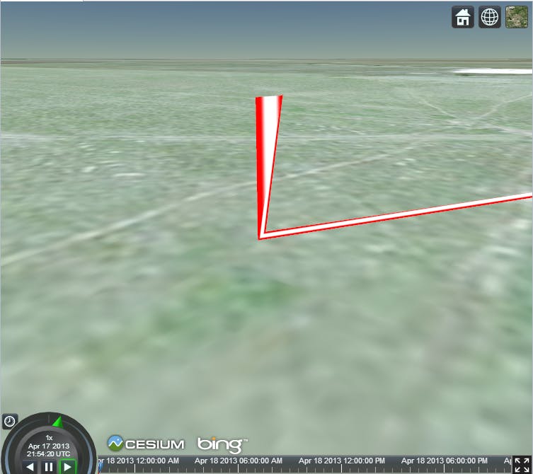
We came across a precision problem when using the compressed normals. When zoomed in close to a polyline end point that has another end point at more than about 90 thousand meters away, the extruded positions will jitter like in the image below:
One solution is to subdivide the line; however, for the access line between theGeoeye 1and theISSshown below, the number of positions goes from 2 to about 50.
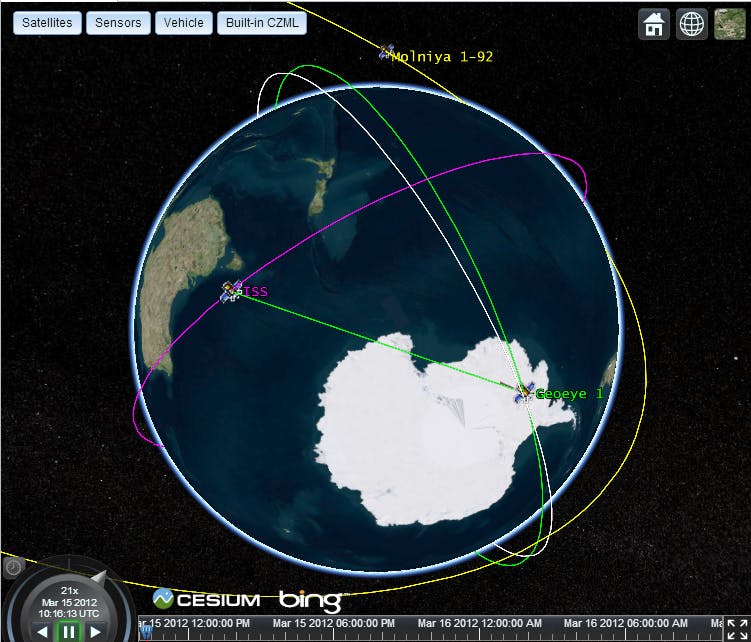
Instead of adding that many additional points for a simple access line, we decided to use the 12 vertex attributes for the current vertex position and the adjacent positions.
After we extrude the positions in screen space, we need to transform the position to clip coordinates for the output of the vertex shader. The final position in screen space is avec4of the modified x and y coordinates, the negative z coordinate and a w coordinate of1.0. We use the negative z coordinate because the view direction is along the negative z axis in every space after and including eye space. The w coordinate is used for the perspective divide which make objects farther from the eye seem smaller. We set the w coordinate to1.0because we want the width to be constant regardless of perspective. This causes an issue when the line intersects the near plane. We then reverse the operations of the viewport transformation to have our final vertex shader output position in clip space. Below shows a line before it intersects the near plane:
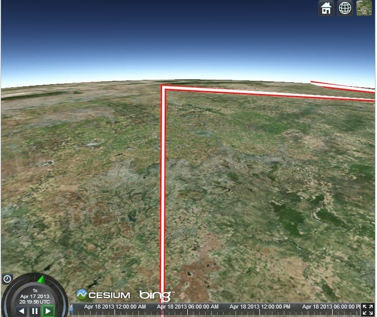
and this next image shows the same line after zooming in that now intersects the near plane:
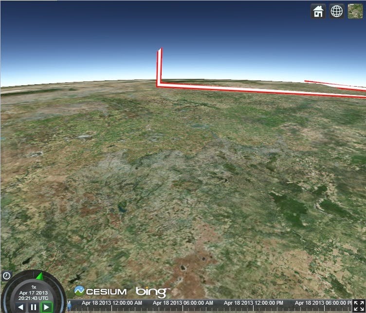
For more information about why this happens, seeClipping using homogeneous coordinates.
To fix this, we need to clip the line to the near plane before transforming to screen space. What if there is a situation such as in the image below:

On the left, two line segments should be clipped by the near plane and they share the same vertex position. The line segments intersect the near plane at the points in the green circles. The position that needs to be clipped is circled in blue. Which green position should we clip the blue position to? Each vertex that is shared by two line segments needs to be duplicated again. For each connected line, each position is duplicated twice at the end points and four times at the shared positions. We also need to know which line segment the position belongs to and clip it in the right direction.
The situation on the right is easier to handle once we have handled the situation on the left. If a vertex position belongs to a line that is culled, simply output clip coordinates that are behind the near plane ensuring that the line is not drawn.
Vertex Shader Details
Extrude Vertex in Screen Space
The diagram below shows a line drawn in black and the same line extruded to a greater width in screen space outlined in red. To extrude the line at the end points, simply move the vertices the desired number of pixels in the direction of the normals to the line segment.
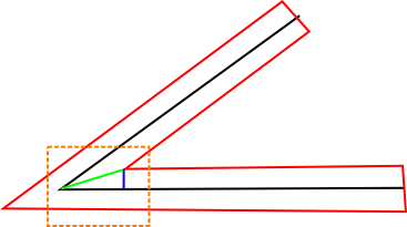
The diagram below shows a close up of the area surrounded by a dashed orange line in the image above. Let the green vector be u and the black vector be v. We want to find the vector u.
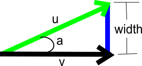
We know the direction of v because it is either the direction to the next point or the previous point on the line. We can find the direction of u because it half-way between the direction to the next and previous points on the line. Now, we just need to find the magnitude of u which, from the trigonometry identity, we know is ||u|| = width / sin(a). We know that for any vectors p and q that ||p x q|| = ||p||||q|||sin(a)|. If we treat û and v̂ as three dimensional vectors in the xy-plane, we can substitute û and v̂ into the expression. Because û and v̂ are unit vectors and the z coordinate is 0.0, the last expression can be simplified to sin(a) = |û.x * v̂.y - û.y * v̂.x|. The GLSL code is given below:
float sinAngle = abs(u.x * v.y - u.y * v.x);
width /= sinAngle;

vec2 offset = direction * directionSign * width * czm_highResolutionSnapScale;
gl_Position = czm_viewportOrthographic * vec4(positionWC.xy + offset, -positionWC.z, 1.0);
Care must be given to make sure that sinAngle is not close to zero and that we move the vertex in the right direction (either u or -u in our example).
Clipping to the Near Plane
As explained above, we need to clip the end points of the line segments to the near plane. Here is the GLSL function used to clip a point to the near plane in eye coordinates:
void clipLineSegmentToNearPlane(
    vec3 p0,
    vec3 p1,
    out vec4 positionWC,
    out bool culledByNearPlane)
{
    culledByNearPlane = false;

    vec3 p1ToP0 = p1 - p0;
    float magnitude = length(p1ToP0);
    vec3 direction = normalize(p1ToP0);
    float endPoint0Distance =  -(czm_currentFrustum.x + p0.z);
    float denominator = -direction.z;

    if (endPoint0Distance < 0.0 && abs(denominator) < czm_epsilon7)
    {
        // the line segment is parallel to and behind
        // the near plane
        culledByNearPlane = true;
    }
    else if (endPoint0Distance < 0.0 && abs(denominator) > czm_epsilon7)
    {
        // ray-plane intersection:
        //  t = (-plane distance - dot(plane normal, ray origin))
        //  t /= dot(plane normal, ray direction);
        float t = (czm_currentFrustum.x + p0.z) / denominator;

        if (t < 0.0 || t > magnitude)
        {
            // the segment intersects the near plane,
            // but the entire segment is behind the
            // near plane
            culledByNearPlane = true;
        }
        else
        {
            // segment intersects the near plane,
            // find intersection
            p0 = p0 + t * direction;
        }
    }

    positionWC = czm_eyeToWindowCoordinates(vec4(p0, 1.0));
}
The comments throughout the function describe the conditions when it is clipped or culled. The function has been simplified based on the assumption that the near plane normal is vec3(0.0, 0.0, -1.0) and is a distance czm_currentFrustum.x from the origin.
Encoding/Decoding Unit Vectors
When we were restricting ourselves to 8 vertex attributes, we encoded the the two unit vectors that pointed to previous and next points on the line using the Spheremap Transform. This allowed us to compress two vec3 vertex attributes into a single vec4 vertex attribute. Below is the Javascript code used to compress a unit vector into two components:
function encode(cartesian) {
    var p = Math.sqrt(cartesian.z * 8.0 + 8.0);
    var result = new Cartesian2();
    result.x = cartesian.x / p + 0.5;
    result.y = cartesian.y / p + 0.5;
    return result;
}
and here is the GLSL code to decompress the unit vector in the vertex shader:
vec3 decode(vec2 enc)
{
    vec2 fenc = enc * 4.0 - 2.0;
    float f = dot(fenc, fenc);
    float g = sqrt(1.0 - f / 4.0);

    vec3 n;
    n.xy = fenc * g;
    n.z = 1.0 - f / 2.0;
    return n;
}
For more information on different ways to compress unit vectors, see Compact Normal Storage for Small G-Buffers.