
CustomPatternSensor#directions, which is an array of clock and cone angles, and a radius
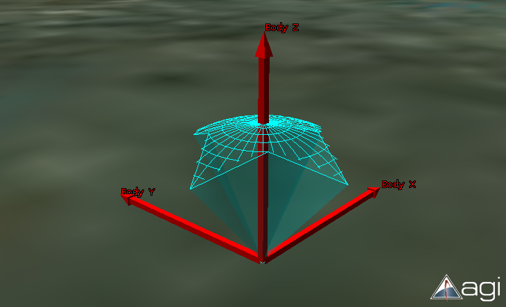
(CustomPatternSensor#radius). The sensor's principal direction is along the positive z-axis. Clock
angles are angles around the z-axis, rotating x into y. Cone angles are angles from the z-axis towards the xy plane.
Directions must conform to the following restrictions:
- Duplicate vertices are not allowed.
- Consecutive vertices should be less than 180 degrees apart.
CustomPatternSensor#showDomeSurfaces.
Code Example 1 below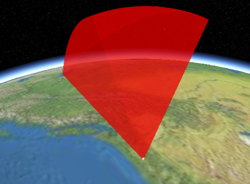 |
Code Example 2 below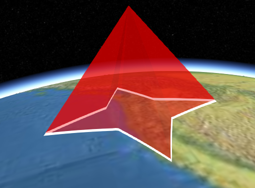 |
Code Example 3 below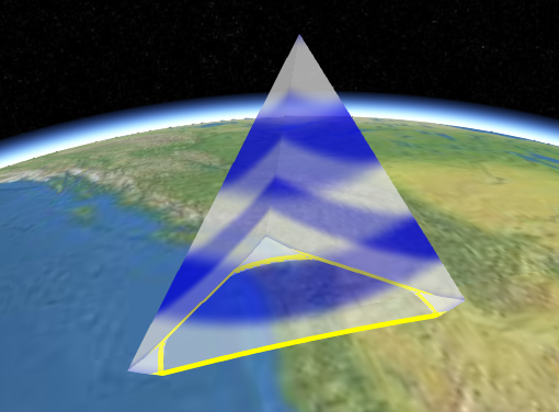 |
Code Example 4 below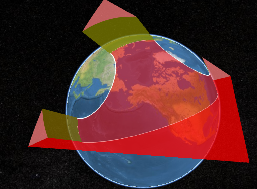 |
A sensor points along the local positive z-axis and is positioned and oriented using
CustomPatternSensor#modelMatrix.
| Name | Type | Description | ||||||||||||||||||||||||||||||||||||||||||||||||||||||||||||||||||||||||||||||||||||||||||||||||||||||||||||||||||||||||||||||||||||||||||||
|---|---|---|---|---|---|---|---|---|---|---|---|---|---|---|---|---|---|---|---|---|---|---|---|---|---|---|---|---|---|---|---|---|---|---|---|---|---|---|---|---|---|---|---|---|---|---|---|---|---|---|---|---|---|---|---|---|---|---|---|---|---|---|---|---|---|---|---|---|---|---|---|---|---|---|---|---|---|---|---|---|---|---|---|---|---|---|---|---|---|---|---|---|---|---|---|---|---|---|---|---|---|---|---|---|---|---|---|---|---|---|---|---|---|---|---|---|---|---|---|---|---|---|---|---|---|---|---|---|---|---|---|---|---|---|---|---|---|---|---|---|---|---|
options |
Object |
optional
Object with the following properties:
|
Examples:
// Example 1. Sensor on the ground pointing straight up
var sensor = scene.primitives.add(new IonSdkSensors.CustomPatternSensor({
  modelMatrix : Cesium.Transforms.eastNorthUpToFixedFrame(Cesium.Cartesian3.fromDegrees(-123.0744619, 44.0503706)),
  radius : 1000000.0,
  directions : [{
    clock : Cesium.Math.toRadians(0.0),
    cone : Cesium.Math.toRadians(30.0)
  }, {
    clock : Cesium.Math.toRadians(90.0),
    cone : Cesium.Math.toRadians(30.0)
  }, {
    clock : Cesium.Math.toRadians(180.0),
    cone : Cesium.Math.toRadians(30.0)
  }]
}));
// Example 2. Star-pattern sensor pointing straight down with its lateral surface intersecting the ellipsoid.
var sensor = scene.primitives.add(new IonSdkSensors.CustomPatternSensor({
modelMatrix : Cesium.Transforms.northEastDownToFixedFrame(Cesium.Cartesian3.fromDegrees(-123.0744619, 44.0503706, 700000.0)),
radius : 1000000.0,
directions : [{
clock : Cesium.Math.toRadians(0.0),
cone : Cesium.Math.toRadians(40.0)
}, {
clock : Cesium.Math.toRadians(45.0),
cone : Cesium.Math.toRadians(20.0)
}, {
clock : Cesium.Math.toRadians(90.0),
cone : Cesium.Math.toRadians(40.0)
}, {
clock : Cesium.Math.toRadians(135.0),
cone : Cesium.Math.toRadians(20.0)
}, {
clock : Cesium.Math.toRadians(180.0),
cone : Cesium.Math.toRadians(40.0)
}, {
clock : Cesium.Math.toRadians(225.0),
cone : Cesium.Math.toRadians(20.0)
}, {
clock : Cesium.Math.toRadians(270.0),
cone : Cesium.Math.toRadians(40.0)
}, {
clock : Cesium.Math.toRadians(315.0),
cone : Cesium.Math.toRadians(20.0)
}],
}));// Example 3. Sensor pointing straight down with its dome intersecting the ellipsoid
var sensor = scene.primitives.add(new IonSdkSensors.CustomPatternSensor({
modelMatrix : Cesium.Transforms.northEastDownToFixedFrame(Cesium.Cartesian3.fromDegrees(-123.0744619, 44.0503706, 900000.0)),
radius : 1000000.0,
directions : [{
clock : Cesium.Math.toRadians(270.0),
cone : Cesium.Math.toRadians(30.0)
}, {
clock : Cesium.Math.toRadians(0.0),
cone : Cesium.Math.toRadians(30.0)
}, {
clock : Cesium.Math.toRadians(90.0),
cone : Cesium.Math.toRadians(30.0)
}],
lateralSurfaceMaterial : Cesium.Material.fromType(Cesium.Material.StripeType),
intersectionColor : Cesium.Color.YELLOW
}));// Example 4. Sensor with custom materials for each surface. Switch to 2D to see the ellipsoid surface material.
var sensor = scene.primitives.add(new IonSdkSensors.CustomPatternSensor({
modelMatrix : Cesium.Transforms.northEastDownToFixedFrame(Cesium.Cartesian3.fromDegrees(-123.0744619, 44.0503706, 9000000.0)),
radius : 20000000.0,
directions : [{
clock : Cesium.Math.toRadians(270.0),
cone : Cesium.Math.toRadians(30.0)
}, {
clock : Cesium.Math.toRadians(0.0),
cone : Cesium.Math.toRadians(30.0)
}, {
clock : Cesium.Math.toRadians(90.0),
cone : Cesium.Math.toRadians(30.0)
}],
lateralSurfaceMaterial : Cesium.Material.fromType(Cesium.Material.ColorType, { color : new Cesium.Color(1.0, 0.0, 0.0, 0.5) }),
ellipsoidHorizonSurfaceMaterial : Cesium.Material.fromType(Cesium.Material.ColorType, { color : new Cesium.Color(0.0, 1.0, 0.0, 0.5) }),
ellipsoidSurfaceMaterial : Cesium.Material.fromType(Cesium.Material.ColorType, { color : new Cesium.Color(0.0, 0.0, 1.0, 0.5) }),
domeSurfaceMaterial : Cesium.Material.fromType(Cesium.Material.ColorType, { color : new Cesium.Color(1.0, 1.0, 1.0, 0.5) })
}));See:
Members
classificationType : ClassificationType
packages/ion-sdk-sensors/Source/Scene/CustomPatternSensor.js 703
-
Default Value:
ClassificationType.BOTH
When true, draws the bounding sphere for each DrawCommand in the sensor.
-
Default Value:
false
When true, draws the points where the sensor boundary crosses off of and onto the ellipsoid.
-
Default Value:
false
When true, draws the proxy geometry used for shading the dome and ellipsoid horizon surfaces of the sensor boundary.
-
Default Value:
false
When true, draws a bounding volume around the light source for the shadow map used for environment intersections.
Also, the contents of the shadow map are drawn to a viewport quad.
-
Default Value:
false
The sensor's principal direction is along the positive z-axis. Clock angles are angles around the z-axis, rotating x into y. Cone angles are angles from the z-axis towards the xy plane.
Directions must conform to the following restrictions:
- Duplicate vertices are not allowed.
- Consecutive vertices should be less than 180 degrees apart.
Example:
// Create a triangular sensor projection
sensor.directions = [{
    clock : Cesium.Math.toRadians(0.0),
    cone : Cesium.Math.toRadians(30.0)
  }, {
    clock : Cesium.Math.toRadians(90.0),
    cone : Cesium.Math.toRadians(30.0)
  }, {
    clock : Cesium.Math.toRadians(180.0),
    cone : Cesium.Math.toRadians(30.0)
}]
domeSurfaceMaterial : Material
packages/ion-sdk-sensors/Source/Scene/CustomPatternSensor.js 497
Material objects or a custom material, scripted with
Fabric.
When undefined, CustomPatternSensor#lateralSurfaceMaterial is used.
-
Default Value:
undefined
Examples:
// Change the color of the dome surface material to yellow
sensor.domeSurfaceMaterial.uniforms.color = Cesium.Color.YELLOW;
// Change material to horizontal stripes
sensor.domeSurfaceMaterial = Material.fromType(Material.StripeType);See:
readonly ellipsoid : Ellipsoid
packages/ion-sdk-sensors/Source/Scene/CustomPatternSensor.js 888
-
Default Value:
Ellipsoid.WGS84
ellipsoidHorizonSurfaceMaterial : Material
packages/ion-sdk-sensors/Source/Scene/CustomPatternSensor.js 409
Material objects or a custom material, scripted with
Fabric.
When undefined, CustomPatternSensor#lateralSurfaceMaterial is used.
-
Default Value:
undefined
Examples:
// Change the color of the ellipsoid horizon surface material to yellow
sensor.ellipsoidHorizonSurfaceMaterial.uniforms.color = Cesium.Color.YELLOW;
// Change material to horizontal stripes
sensor.ellipsoidHorizonSurfaceMaterial = Cesium.Material.fromType(Cesium.Material.StripeType);See:
ellipsoidSurfaceMaterial : Material
packages/ion-sdk-sensors/Source/Scene/CustomPatternSensor.js 457
Material objects or a custom material, scripted with
Fabric.
When undefined, CustomPatternSensor#lateralSurfaceMaterial is used.
-
Default Value:
undefined
Examples:
// Change the color of the ellipsoid surface material to yellow
sensor.ellipsoidSurfaceMaterial.uniforms.color = new Cesium.Color.YELLOW;
// Change material to horizontal stripes
sensor.ellipsoidSurfaceMaterial = Material.fromType(Material.StripeType);See:
true, a sensor intersecting the environment, e.g. terrain or models, will discard the portion of the sensor that is occluded.
-
Default Value:
false
environmentIntersectionColor : Color
packages/ion-sdk-sensors/Source/Scene/CustomPatternSensor.js 631
-
Default Value:
Color.WHITE
environmentIntersectionWidth : Number
packages/ion-sdk-sensors/Source/Scene/CustomPatternSensor.js 641
-
Default Value:
5.0
environmentOcclusionMaterial : Material
packages/ion-sdk-sensors/Source/Scene/CustomPatternSensor.js 606
-
Default Value:
Material.ColorType-
Default Value:
undefined
See:
intersectionColor : Color
packages/ion-sdk-sensors/Source/Scene/CustomPatternSensor.js 549
-
Default Value:
Color.WHITESee:
-
Default Value:
5.0
See:
lateralSurfaceMaterial : Material
packages/ion-sdk-sensors/Source/Scene/CustomPatternSensor.js 363
Material objects or a custom material, scripted with
Fabric.
-
Default Value:
Material.ColorTypeExamples:
// Change the color of the default material to yellow
sensor.lateralSurfaceMaterial.uniforms.color = Cesium.Color.YELLOW;
// Change material to horizontal stripes
sensor.lateralSurfaceMaterial = Cesium.Material.fromType(Cesium.Material.StripeType);See:
modelMatrix : Matrix4
packages/ion-sdk-sensors/Source/Scene/CustomPatternSensor.js 343
-
Default Value:
Matrix4.IDENTITYExample:
// The sensor's origin is located on the surface at -75.59777 degrees longitude and 40.03883 degrees latitude.
// The sensor opens upward, along the surface normal.
var center = Cesium.Cartesian3.fromDegrees(-75.59777, 40.03883);
sensor.modelMatrix = Cesium.Transforms.eastNorthUpToFixedFrame(center);
portionToDisplay : SensorVolumePortionToDisplay
packages/ion-sdk-sensors/Source/Scene/CustomPatternSensor.js 320
COMPLETE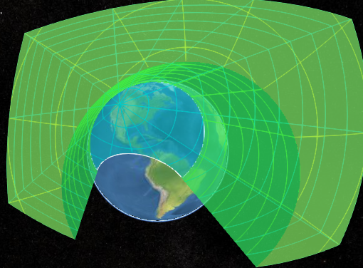 |
BELOW_ELLIPSOID_HORIZON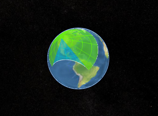 |
ABOVE_ELLIPSOID_HORIZON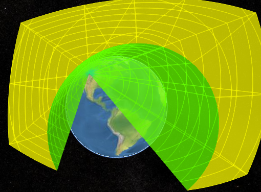 |
-
Default Value:
SensorVolumePortionToDisplay.COMPLETE-
Default Value:
Number.POSITIVE_INFINITYtrue, the sensor is shown.
-
Default Value:
true
true, the sensor dome surfaces are shown.
These surfaces are only shown in 3D (see Scene#mode).
Full sensor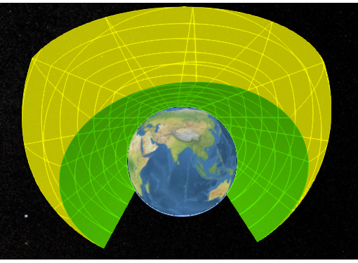 |
Dome only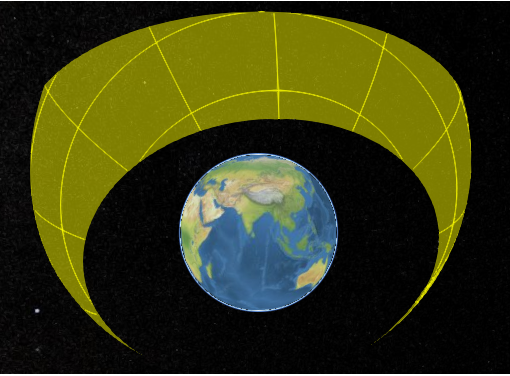 |
-
Default Value:
true
See:
showEllipsoidHorizonSurfaces : Boolean
packages/ion-sdk-sensors/Source/Scene/CustomPatternSensor.js 434
true, the ellipsoid horizon surfaces, i.e., the sides formed from occlusion due to the ellipsoid horizon, are shown.
These surfaces are only shown in 3D (see Scene#mode).
Full sensor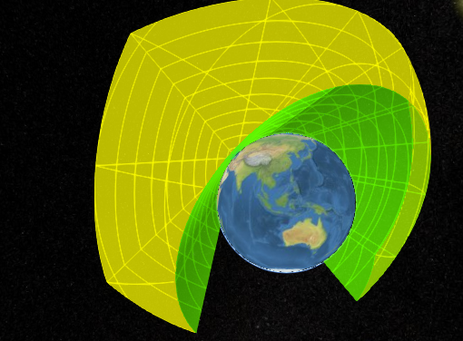 |
Ellipsoid horizon surfaces only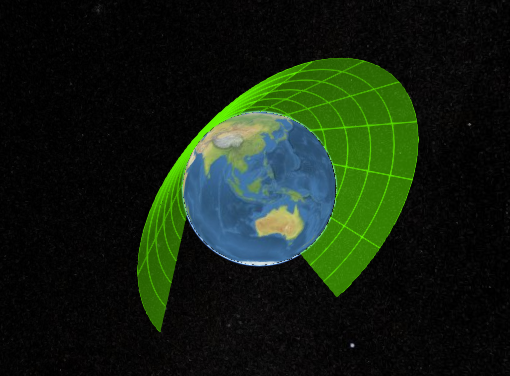 |
-
Default Value:
true
See:
true, the ellipsoid/sensor intersection surfaces are shown.
These surfaces are only shown in 2D and Columbus View (see Scene#mode).
-
Default Value:
true
See:
showEnvironmentIntersection : Boolean
packages/ion-sdk-sensors/Source/Scene/CustomPatternSensor.js 621
true, a line is shown where the sensor intersects the environment, e.g. terrain or models.
-
Default Value:
false
true, the portion of the sensor occluded by the environment will be drawn with CustomPatternSensor#environmentOcclusionMaterial.
CustomPatternSensor#environmentConstraint must also be true.
-
Default Value:
false
true, a polyline is shown where the sensor intersects the ellipsoid.
showIntersection : false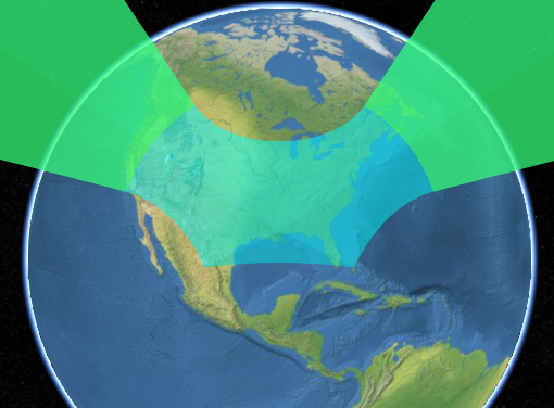 |
showIntersection : true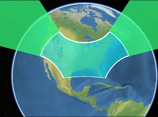 |
-
Default Value:
true
See:
true, the sensor's lateral surfaces, i.e., the outer sides of the sensor, are shown.
These surfaces are only shown in 3D (see Scene#mode).
Full sensor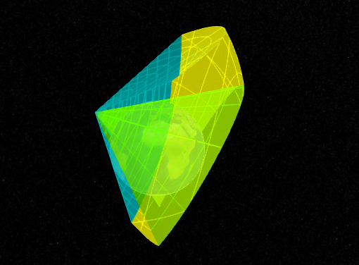 |
Lateral surfaces only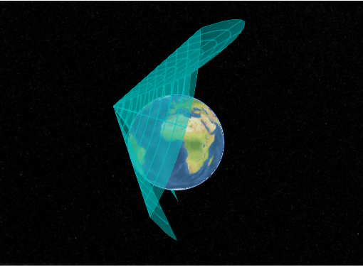 |
-
Default Value:
true
See:
When true, a sensor intersecting the ellipsoid is drawn through the ellipsoid and potentially out
to the other side.
showThroughEllipsoid : false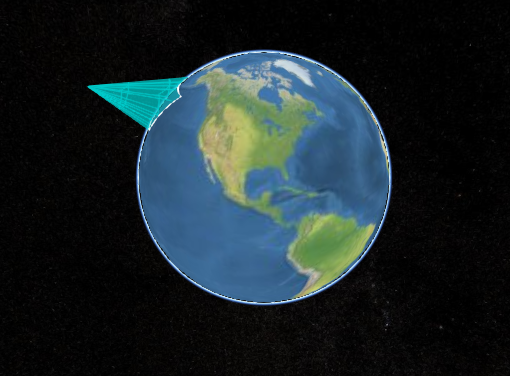 |
showThroughEllipsoid : true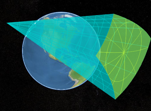 |
-
Default Value:
false
Scene#mode.)
-
Default Value:
false
Experimental
This feature is not final and is subject to change without Cesium's standard deprecation policy.
See:
viewshedOccludedColor : Color
packages/ion-sdk-sensors/Source/Scene/CustomPatternSensor.js 681
-
Default Value:
Color.REDExperimental
This feature is not final and is subject to change without Cesium's standard deprecation policy.
-
Default Value:
2048
Experimental
This feature is not final and is subject to change without Cesium's standard deprecation policy.
viewshedVisibleColor : Color
packages/ion-sdk-sensors/Source/Scene/CustomPatternSensor.js 669
-
Default Value:
Color.LIMEExperimental
This feature is not final and is subject to change without Cesium's standard deprecation policy.
Methods
static IonSdkSensors.CustomPatternSensor.ellipsoidSurfaceIn3DSupported(scene) → Boolean
packages/ion-sdk-sensors/Source/Scene/CustomPatternSensor.js 2523
| Name | Type | Description |
|---|---|---|
scene |
Scene | The scene. |
Returns:
true if ellipsoid surface shading is supported in 3D mode; otherwise, returns false
static IonSdkSensors.CustomPatternSensor.viewshedSupported(scene) → Boolean
packages/ion-sdk-sensors/Source/Scene/CustomPatternSensor.js 2533
| Name | Type | Description |
|---|---|---|
scene |
Scene | The scene. |
Returns:
true if viewshed shading is supported; otherwise, returns false
Once an object is destroyed, it should not be used; calling any function other than
isDestroyed will result in a DeveloperError exception. Therefore,
assign the return value (undefined) to the object as done in the example.
Returns:
Throws:
-
DeveloperError : This object was destroyed, i.e., destroy() was called.
Example:
sensor = sensor && sensor.destroy();If this object was destroyed, it should not be used; calling any function other than
isDestroyed will result in a DeveloperError exception.
Returns:
true if this object was destroyed; otherwise, false.
Viewer or CesiumWidget render the scene to
get the draw commands needed to render this primitive.
Do not call this function directly. This is documented just to list the exceptions that may be propagated when the scene is rendered:
Throws:
-
DeveloperError : this.radius must be greater than or equal to zero.
-
DeveloperError : this.lateralSurfaceMaterial must be defined.